FABRICATION OF A FEED MIXER
As an Agricultural Engineer, we design machines and equipments used for food processing,harvesting,planting e.t.c During my course of industrial training,we got to design different machines which i would share with you. I would start with FEED MIXER
FEED MIXER
Feed mixers are used in feed mills for the mixing of feed ingredients and premixes. The mixer plays a vital role in the feed production process, with efficient mixing being the key to good feed production. If feed is not mixed properly, ingredients and nutrients will not be properly distributed when it comes time to extrude and pelletize the feed, or if the feed is to be used as mash. This means that not only would the feed not have nutritional benefit, it would be bad for the animals that are eating it.
Materials Used For Fabrication
- Angle Iron
- Electrode
- Paint brush
- Red oxide primer
- Bolts and nut
- Metal sheets
- Steel chalk
- Cutting disc
- Grinding disc
Tools Used
- Hammer
- paint can
- Steel rule
- Scriber
- Try square
- Welding tong
- Measuring tape
- Hacksaw with
- blade
- Drill bit
- F-clamp
- Measuring rope
- Sledge hammer
- Centre punch
- Divider
Machines used
- Cutting machine
- Grinding machine
- Arc-welding machine
- Oxyacetylene gas
- Pillar drilling machine
Procedures
Step 1:- Making of the conical section
- Two metal sheets were placed on the floor side by side; diameter 20ʺ was done on the end of the first metal sheet and diameter 8ʺ on the end of the other sheet. The difference between the large and small diameter was found. Centre Punch was used to get the centre of the circle.
Large diameter – small diameter= 20ʺ - 8ʺ = 12ʺ
The large diameter was multiplied by the vertical height/slant height
Vertical height × large diameter =22ʺ × 20ʺ =440ʺ
440ʺ was divided by the product of the difference in diameter
440ʺ÷ 12ʺ = 36.66ʺ
36.66ʺ is the length of the centre line needed from the top of the cone to the intersection point. - A cone shaped was then cut out of the metal sheet
- The already cut cone metal sheet was rolled into a coned shaped using a roller.
- The rolled cone metal sheet was tacked and welded by an arc welding machine to form the frustum part of the feed mixer.
Step 2:- Making of the cylindrical section
- Diameter 440ʺ was measured and marked out on the metal sheets
- The already cut metal sheets were rolled into a cylindrical shape using a roller.
- The rolled cylinder was tacked and rolled together using an arc welding machine making an assembly.
Step 3:-
- The rolled cone metal sheet was joined and welded together with the rolled cylindrical metal sheet
- The four stands of the mixer were measured, marked out and cut out of the angle iron.
- The stands were welded to the assembly.
- The stands were also braced.
- The discharge section was measured, marked out and cut.
- The bucket section was also measured, marked out and cut.
- The discharge and bucket section were welded to the assembly.
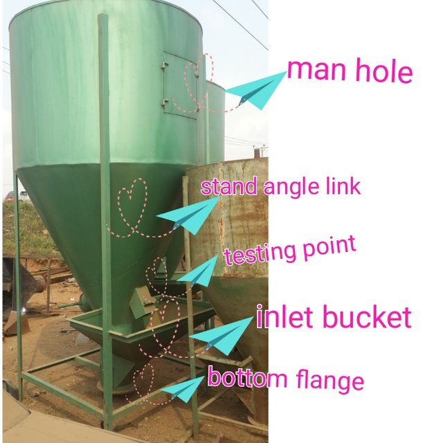
- The bottom flange was also welded to the assembly.
- The finishing outlet was also measured, marked out and cut.
- Organ blade was cut out using oxy-acetylene gas.
- The organ blade was then bent and welded to the plain rod.
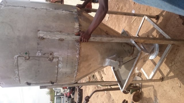
- The finishing outlet and welded organ blade were welded to the assembly, all to form a feed mixer.
- Full welding and grinding was carried out to make the work neat.
- Finally application of green oxide prime was done on the fabricated feed mixer using paint can and brush.
Thanks for reading....your lady student Engineer @jeaniepearl

Beautifully written
Thanks cuties
Efficient engineer!. Well done cutie.
Thanks mr whale
Hahahaha Jeanie...you too? I receive it.
Well done my pretty engineer! You got a "crush" on my Whatsapp Group oo....didn't take down your bday picture and so you acquired an admirer
Hahahhahahaha thanks my lady
Tell him not to crush on,its the work of make up ,a good hair do by @adejoke16 and then the photographer
Lmao
STOP