Arduino Remote Home #9
I find it ironic that the garage portion of this project is the closing part of this blog, at least for now. The irony is that a left open garage door, is the whole reason I committed to doing this Home Automation project. This will be the most detailed part and may get lengthy. With no further a do.
At the start I was thinking of putting an Uno with a wifi shield set to be a web-server in the garage. But after considering environmental conditions I decided against it. So in order to accomplish my objectives plus have spare capacity for the future, I needed to install some wires between the house and garage. After figuring/engineering the Garage I/O board, and garage control box, plus factoring in the LED indicators and door operator signals for both garage doors, I ended up needing 31 conductors. Just so happened that I had a partial spool of 18 gauge, 8-conductor cable. I ended up installing 4 of them in a 1” pvc conduit. So in keeping up with the idea of zero indexing, I opted to label the Cables, C0,C1,C2 and C3. I took very detailed notes of how each cable and colored wire terminated at each end. The center image here shows the the garage end of them. From left to right you see the color pattern: Brown,Blue,Yellow,Orange,Black,Green,Red and White.
No particular reason, just kept the pattern consistent. 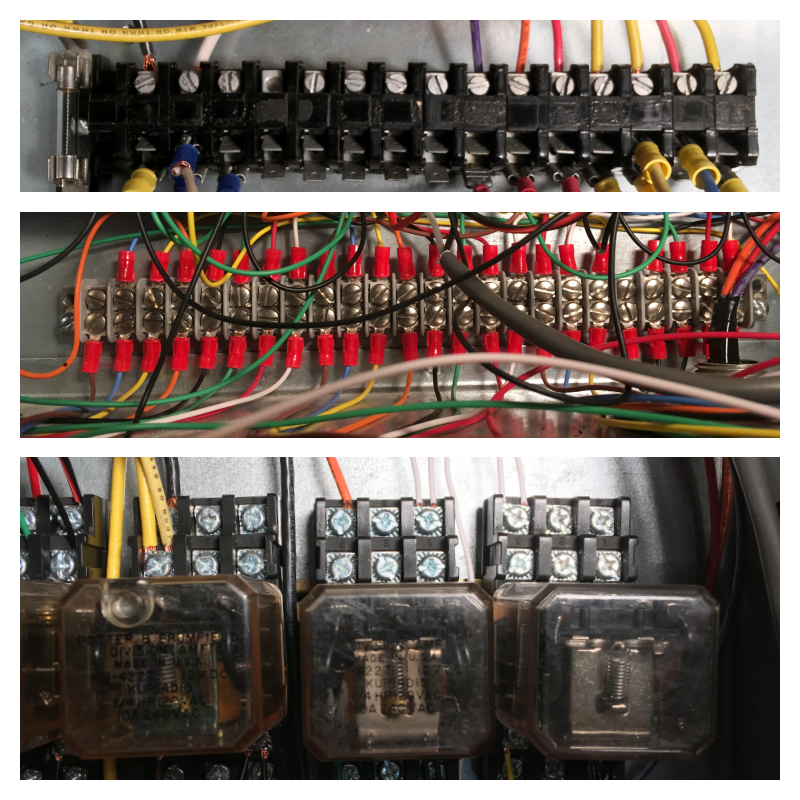 The top image shows the 120volt AC terminal strip. I made notes on each of those wires as well. I should mention that it is standard practice to install incoming, 120 vac power feeds, the “line”, at the top of any field installed enclosure. So to be congruent with that idea, I placed that terminal strip at the top. Additionally I installed a fuse as close to the “line” entrance point as possible. Then placed the black hot and white neutral wires next to the fuse. I left a gap to visually separate the colored wires which are the loads, typically at the bottom of an enclosure. Finally the bottom image shows three 3pole double throw, 12vdc “ice cube” relays. The view shows to rows of screws. The lower is the normally open,”N.O.” and the top normally closed, “N.C.” Not shown are the 3 commons and the coil +/-. Three of these relays are energized when the web-server receives a single to write a pin high or low, thus controlling a 120 vac load. Working right to left these loads are, spare, 120v signal to a different relay coil for fence plug source selector and the interior garage lights. The far left relay has a 120 vac coil and was an add on to control the garage green LED anode. The coil is controlled by a photocell so that when it is dark the power to the green LED first goes through the little PWM device.
 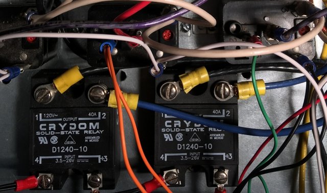 These two SSR’s are rated at 120 vac, 40amps. Over kill for sure, as the circuit breaker feeding them is only rated at 20amps. Use what you have, is my motto. The left one gets its input signal “automatically” via the exterior plug control section in the Admin tab of the web page and is the exclusive way the exterior garage plug is controlled. The right one is also controlled by the Admin tab but it sends power to the fence plug when in “auto” mode. The five sealed, black relays are 120vac coils, SPST. They send a 12vdc signal back to the input mega via the Garage I/O board to monitor the various conditions, photocell, garage door opener motor(x2), fence plug and exterior outlet.
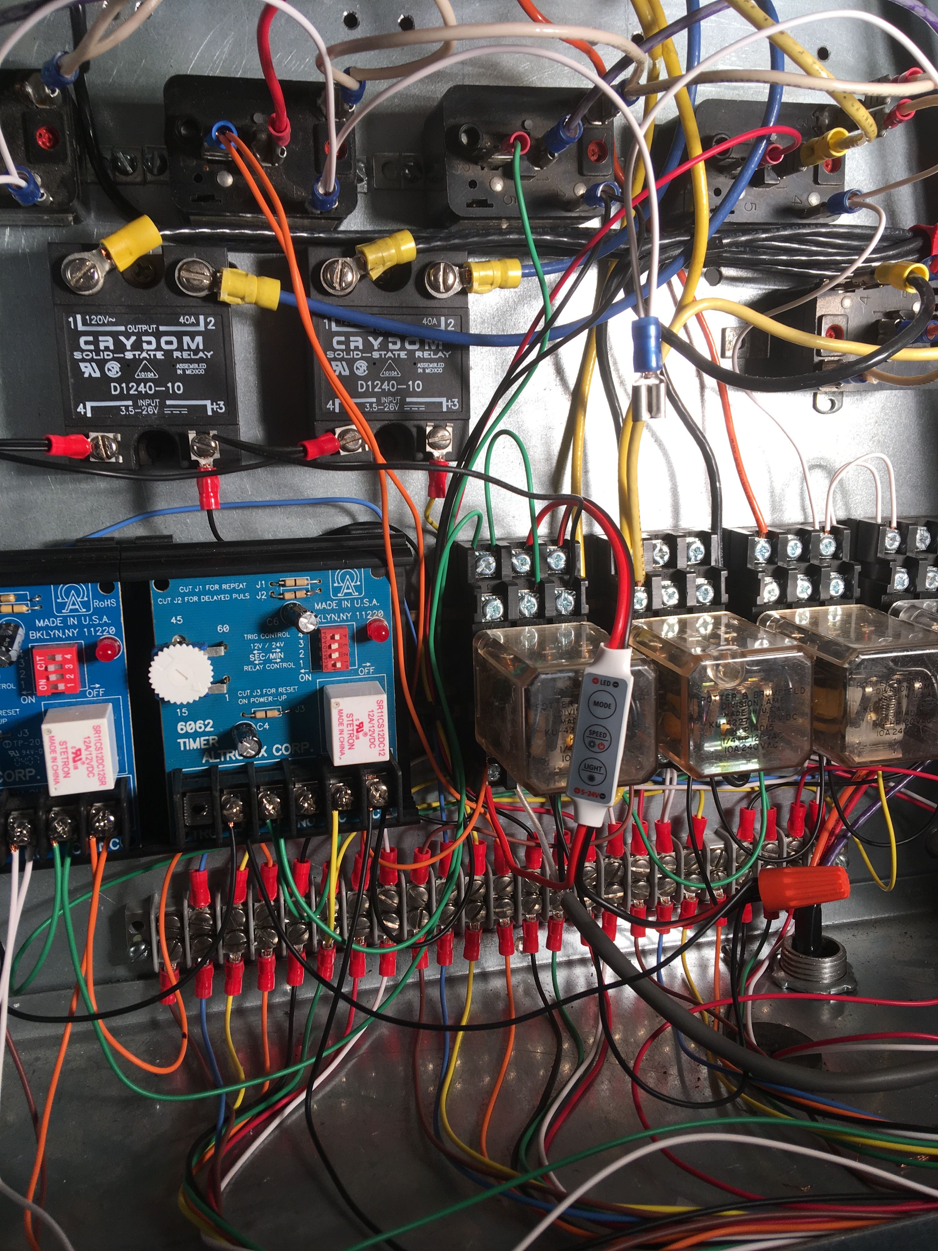 The last two items are the timers that control the garage door status.
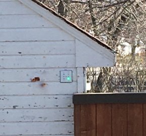
Here you see the bottom right LED solid green, indicating right door closed and locked.
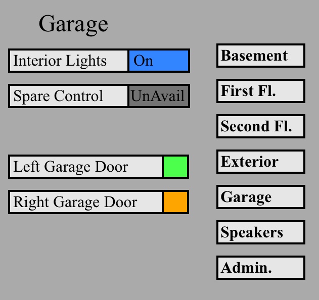
And finally when the door is open everything goes red. Here is a schematic I drew up using Fritzing. I had to improvise on some of the symbols. The schematic shows the door closed and locked while the photocell output is off.
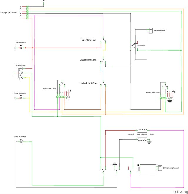
I’m only going over a few key items. Top left connecter represents the bottom terminal strip mention above.
Connection 1: ground—C3 black
Connection 2: Arduino input pin 13>>right door locked status—C0 orange
Connection 3: Arduino input pin 11>>right door opener running status—C0 green
Connection 4: Arduino input pin 12>>right door stall status—C0 black
Connection 5: +12vdc—C3 white
Connection 6: Arduino input pin 10>>right door open status—C3 red
The label “from GDO motor” relates to right hand relay shown here.
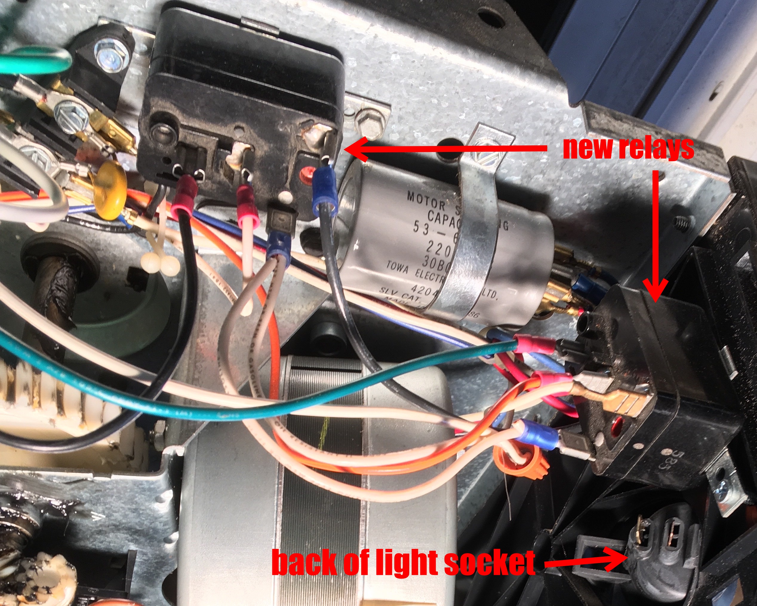 I connected the relay coil to the run capacitor so that regardless of the motors direction of rotation I get a contact closure ie: Arduino pin 11 goes high indicating the motor is running. I moved the light socket wires to other relays coil, so that rather than turning on just one bulb I turn on all the garage lights.
As mentioned before, this was Phase I. There are still some loose ends to this phase that I’m in the process of finishing. Phase II will be a second control box for the second floor. That will finish out all the general house monitoring and control stuff. Phase III will be adding washer and dryer monitoring that will text the user when the cycle is done. And the final Phase will be controls for a solar water heating system, along with some other resource conservation ideas I’ve been tossing around. Those will require lots of monitoring, controls and redundancies for safety. Should be fun. This will wrap up posting for now. I’ll be sure to get back as progress occurs.
On a larger scale, I think I know what my next two Arduino, or maybe, RaspberryPi projects will be. They will be independent but compliment each other. The projects revolve around model railroading. One will be modeling a shipping port that has automated gantry cranes and ground support vehicles that will move shipping containers between ships, holding yards, intermodal rail-cars and semi-trailers. I see myself learning and using 3D printing for this, as I haven't been able to find suitable models of these machines. The second will be using RFID tags to trac and direct where the containers get shipped to and from. Both of these projects are going to be new skills and money intensive. I know I can learn the skills. Now I need Bitcoin to hit $200,000.00 :)
As always, I’m glad to answer any questions.
Join our Discord Channel to connect with us and nominate your own or somebody else's posts in our review channel.
Help us to reward you for making it ! Join our voting trail or delegate steem power to the community account.
Your post is also presented on the community website www.steemmakers.com where you can find other selected content.
If you like our work, please consider upvoting this comment to support the growth of our community. Thank you.
Congratulations @electricswine! You have completed some achievement on Steemit and have been rewarded with new badge(s) :
Click on any badge to view your own Board of Honor on SteemitBoard.
For more information about SteemitBoard, click here
If you no longer want to receive notifications, reply to this comment with the word
STOP