아두이노 코딩-88: MPU6050 센서 사용 Pitching(피칭), Rolling(롤링), Yawing(야잉)각 측정
아두이노의 IMU(Inertial Measurement Unit: 관성 측정)) 센서인 MPU6050 센서의 기초적인 사용법을 알아보자. MPU6050 으로는 6개의 물리량 측정이 가능하다. 즉 3개의 가속도와 3개의 각속도를 뜻한다. 3개의 각속도는 아래 그림을 참조해 보면 Pitching, Rolling 및 Yawing을 뜻한다. 가속도는 MPU6050 보드에 좌표축이 표시되어 있으며 Z축은 수직방향인데 아래쪽이 양의 방향이다.
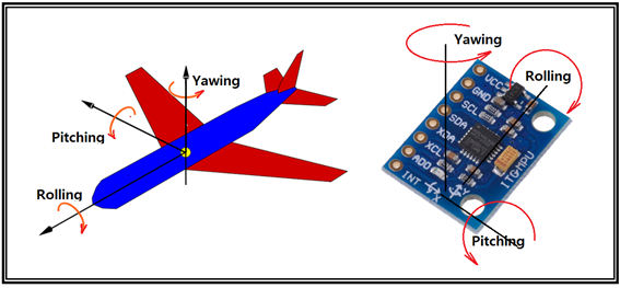
한편 각속도 중에서 Pitching은 비행기 기수의 상승 또는 하강 모션에 해당하며 Rolling은 항공기 기체가 옆으로 구르는 모션이다. 자동차에서는 차량이 논두렁으로 굴러 추락하게 되면 이를 Rolling 또는 전복이라 표현한다. Yawing은 항공기 기체 전체가 평면상에서 회전하게 되는 경우이다. 자동차로 치면 U턴하게 되면 360도 Yawing 한 셈이 된다.
2000cc 급 중형 차량에서는 대개 VDC(vehicle Dynamics Control)시스템이 있어 빙판에서 한쪽이 결빙되어 미끌어질 경우 차량이 스핀을 먹게되는데 Yaw 센서가 회전 모멘트를 감지하게 되면 엔진 출력을 확 줄여주고 ABS로 마찰력을 생성함과 동시에 가볍게 거의 U턴하는 모양세로 멈추게 되는 것이다.
MPU6050센서는 드론에서 흔히 사용되고 있으며 주로 각속도 측정에 사용되며 이러한 기능을 감안하여 자이로 센서라 부르기도 한다. 하지만 드론이나 드론 조종기에서 Pitching은 드론이 앞뒤방향으로 기울어진 상태에서 전진 또는 후진을 뜻하며 Rolling은 좌우로 기울어진 상태에서 좌진 또는 우진을 뜻한다. 이러한 점들이 드론과 비행기와 다른 점이다. Yawing 은 동일하다.
아두이노 보드와 동일한 평면상에 설치된 MPU6050 센서를 사용하여 아두이노 보드의 Pitching 및 Rolling 각도를 측정하는 쥬프 브로킹의(Joop Brokking) 홈페이지에 올려둔 오픈 소스 코드를 참조하기로 하자.
필자도 쥬프 브로킹의 450mm 사이즈 오픈소스 아두이노 드론 제작법에 따라 250mm 아두이노 드론 리모델링에 브로킹의 코드를 사용해서 튜닝 해본 결과 인정할 수밖에 없을 정도로대단히 우수한 드론용 오픈소스임을 알게 되었다.
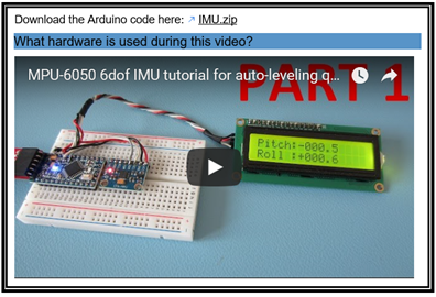
MPU6050을 이용한 기울어진 각을 측정하기 위한 브로킹의 오픈소스 IMU.zip 파일은 다음 주소에서 다운 받을 수가 있다.
http://www.brokking.net/imu.html
브로킹은 아두이노 우노 보드가 아닌 아두이노 나노 보드를 사용한듯하다. 하지만 여기서는 아두이노 우노 보드를 사용하여 코딩을 하기로 하자. 우선 이 파일을 다운받아 아두이노 우노에 설치하고 컴파일해보면 I2C 인터페이스 lcd 디스플레이 관련 문법 에러가 하나 내지는 두개가 발생한다.
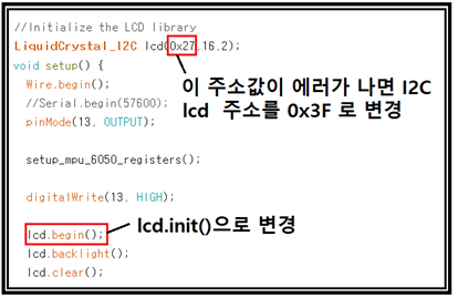
I2C 인터페이스 방식의 lcd를 사용함에 있어서 lcd 의 주소가 0x27 로 되어 있는데 우리가 시중에서 구입하는 많은 lcd 들이 0x3F 가 많은 편이므로 수정하면 된다.
아울러 I2C 인터페이스가 아닌 그냥 lcd 인터페이스에서 사용하는 시작 명령이 lcd.begin() 이며 반면에 I2C 인터페이스에서는 lcd.int()을 사용하도록 하자.
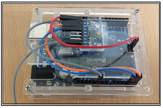
아래의 MPU6050 배선은 인터렵트 배선을 사용하지 않는 방식이다. 아울러 I2C lcd 배선을 위해서도 5V 전원이 하나 더 필요한데 사진에서처럼 SPI 인터페이스 영역에 5V 핀이 있으므로 암커넥터형 점퍼선을 사용하면 된다. SDA 와 SCL 또는 A4와 A5 en 세트가 있으므로 충족이 된다. I2C 배선이 2개가 있드라도 각각 사용하는 주소가 다르기 때문에 아무런 문제가 되지 않는다.
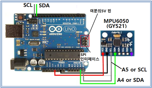
다음 사진은 아두이노 우노 아크릴 박스 위에 MPU6050을 설치하고 SPI 인터페이스 5V핀을 사용하여 배선한 사례이며 아래로 나온 회색 점퍼선은 Interrupt 로 가는 배선이다.
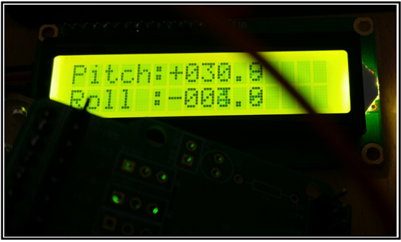
브로킹의 원 코드를 컴퍼일 업로딩하여 실행해 보면 Pitching 과 Rolling 2개의 데이터가 정밀하게 디스플레이 된다. 추가로 Yawing 데이터까지 디스플레이 하려면 코드를 수정해야 한다. 따라서 그러한 번거로움을 피하기 위하여 아예 Yawing 만 단독으로 시리얼 모니터를 사용하여 관찰하도록 한다. 아울러 setup()에서 통신속도는 반드시 57600을 그대로 사용하기 바란다. 만약에 다른 변수를 디스플레이하기 위해서 추가할 경우 브로킹의 오픈소스 코드가 내부적으로 준수하는 4 msec의 주기를 파훼하데 될 경우 병다른 이유 없이 데이터의 정밀도가 떨어질 우려가 있으므로 반드시 주의사항을 지키도록 하자.
아래에 첨부된 MPU_6050_PRY_01 코드는 이러한 목적에 맞춰 수정되어 있으니 브로킹의 사이트를 방문할 필요도 없이 다운받아 사용하기 바란다.
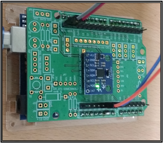
이러한 방법에 의거 아크릴 박스에 부착된 MPU6050센서로 성공적인 실험 후 사제로 제작한 MPU6050 PCB 쉴드를 사용하여 다시 조립하여 실험을 하였다. 하지만 드론용으로 제작한 사제 PCB가 없어도 스카치테이프를 사용하여 MPU6050 보드를 아크릴 박스에 잘 부착하면 실험하는데에 아무런 지장이 없다.
아래는 아두이노를 목측으로 30도 각도 기울인 값 사진이다.
아래의 동영상은 Yawing 이 0에 가까운 중앙 위치에서 Yawing 이 –90이 되도록 우로 90도 Yawing 이 90이 되도록 좌로 90도 회전했다가 다시 중앙 위치에 돌아올 때까지의 시리얼 모니터 데이터 디스플레이 결과이다.
//MPU_6050_PRY_01
#include <LiquidCrystal_I2C.h>
//Include LCD and I2C library
#include <LiquidCrystal_I2C.h>
#include <Wire.h>
//Declaring some global variables
int gyro_x, gyro_y, gyro_z;
long acc_x, acc_y, acc_z, acc_total_vector;
int temperature;
long gyro_x_cal, gyro_y_cal, gyro_z_cal;
long loop_timer;
int lcd_loop_counter;
float angle_pitch, angle_roll, angle_yaw;
int angle_pitch_buffer, angle_roll_buffer;
boolean set_gyro_angles;
float angle_roll_acc, angle_pitch_acc;
float angle_pitch_output, angle_roll_output, angle_yaw_output;
//Initialize the LCD library
LiquidCrystal_I2C lcd(0x3F,16,2);
void setup() {
Wire.begin(); //Start I2C as master
Serial.begin(57600);//Use only for debugging
// Serial.begin(9600);
pinMode(13, OUTPUT); //Set output 13 (LED) as output
setup_mpu_6050_registers(); //Setup the registers of the MPU-6050 (500dfs / +/-8g) and start the gyro
digitalWrite(13, HIGH); //Set digital output 13 high to indicate startup
lcd.init(); //Initialize the LCD
lcd.backlight(); //Activate backlight
lcd.clear(); //Clear the LCD
lcd.setCursor(0,0); //Set the LCD cursor to position to position 0,0
lcd.print(" MPU-6050 IMU"); //Print text to screen
lcd.setCursor(0,1); //Set the LCD cursor to position to position 0,1
lcd.print(" V1.0"); //Print text to screen
delay(1500); //Delay 1.5 second to display the text
lcd.clear(); //Clear the LCD
lcd.setCursor(0,0); //Set the LCD cursor to position to position 0,0
lcd.print("Calibrating gyro"); //Print text to screen
lcd.setCursor(0,1); //Set the LCD cursor to position to position 0,1
for (int cal_int = 0; cal_int < 2000 ; cal_int ++){ //Run this code 2000 times
if(cal_int % 125 == 0)lcd.print("."); //Print a dot on the LCD every 125 readings
read_mpu_6050_data(); //Read the raw acc and gyro data from the MPU-6050
gyro_x_cal += gyro_x; //Add the gyro x-axis offset to the gyro_x_cal variable
gyro_y_cal += gyro_y; //Add the gyro y-axis offset to the gyro_y_cal variable
gyro_z_cal += gyro_z; //Add the gyro z-axis offset to the gyro_z_cal variable
delay(3); //Delay 3us to simulate the 250Hz program loop
}
gyro_x_cal /= 2000; //Divide the gyro_x_cal variable by 2000 to get the avarage offset
gyro_y_cal /= 2000; //Divide the gyro_y_cal variable by 2000 to get the avarage offset
gyro_z_cal /= 2000; //Divide the gyro_z_cal variable by 2000 to get the avarage offset
lcd.clear(); //Clear the LCD
lcd.setCursor(0,0); //Set the LCD cursor to position to position 0,0
lcd.print("Pitch:"); //Print text to screen
lcd.setCursor(0,1); //Set the LCD cursor to position to position 0,1
lcd.print("Roll :"); //Print text to screen
digitalWrite(13, LOW); //All done, turn the LED off
loop_timer = micros(); //Reset the loop timer
}
void loop(){
read_mpu_6050_data(); //Read the raw acc and gyro data from the MPU-6050
gyro_x -= gyro_x_cal; //Subtract the offset calibration value from the raw gyro_x value
gyro_y -= gyro_y_cal; //Subtract the offset calibration value from the raw gyro_y value
gyro_z -= gyro_z_cal; //Subtract the offset calibration value from the raw gyro_z value
//Gyro angle calculations
//0.0000611 = 1 / (250Hz / 65.5)
angle_pitch += gyro_x * 0.0000611; //Calculate the traveled pitch angle and add this to the angle_pitch variable
angle_roll += gyro_y * 0.0000611; //Calculate the traveled roll angle and add this to the angle_roll variable
angle_yaw += gyro_z * 0.0000611;
//0.000001066 = 0.0000611 * (3.142(PI) / 180degr) The Arduino sin function is in radians
angle_pitch += angle_roll * sin(gyro_z * 0.000001066); //If the IMU has yawed transfer the roll angle to the pitch angel
angle_roll -= angle_pitch * sin(gyro_z * 0.000001066); //If the IMU has yawed transfer the pitch angle to the roll angel
//Accelerometer angle calculations
acc_total_vector = sqrt((acc_xacc_x)+(acc_yacc_y)+(acc_zacc_z)); //Calculate the total accelerometer vector
//57.296 = 1 / (3.142 / 180) The Arduino asin function is in radians
angle_pitch_acc = asin((float)acc_y/acc_total_vector) 57.296; //Calculate the pitch angle
angle_roll_acc = asin((float)acc_x/acc_total_vector)* -57.296; //Calculate the roll angle
// Serial.print(" Ax: ");
// Serial.print(acc_x);
// Serial.print(" Ay: ");
// Serial.print(acc_y);
// Serial.print(" Az: ");
// Serial.print(acc_z);
// Serial.print(" P: ");
// Serial.print(angle_pitch);
// Serial.print(" R: ");
// Serial.print(angle_roll);
// Serial.print(" Y: ");
Serial.println(angle_yaw);
//Place the MPU-6050 spirit level and note the values in the following two lines for calibration
angle_pitch_acc -= 0.0; //Accelerometer calibration value for pitch
angle_roll_acc -= 0.0; //Accelerometer calibration value for roll
if(set_gyro_angles){ //If the IMU is already started
angle_pitch = angle_pitch * 0.9996 + angle_pitch_acc * 0.0004; //Correct the drift of the gyro pitch angle with the accelerometer pitch angle
angle_roll = angle_roll * 0.9996 + angle_roll_acc * 0.0004; //Correct the drift of the gyro roll angle with the accelerometer roll angle
}
else{ //At first start
angle_pitch = angle_pitch_acc; //Set the gyro pitch angle equal to the accelerometer pitch angle
angle_roll = angle_roll_acc; //Set the gyro roll angle equal to the accelerometer roll angle
set_gyro_angles = true; //Set the IMU started flag
}
//To dampen the pitch and roll angles a complementary filter is used
angle_pitch_output = angle_pitch_output * 0.9 + angle_pitch * 0.1; //Take 90% of the output pitch value and add 10% of the raw pitch value
angle_roll_output = angle_roll_output * 0.9 + angle_roll * 0.1; //Take 90% of the output roll value and add 10% of the raw roll value
write_LCD(); //Write the roll and pitch values to the LCD display
while(micros() - loop_timer < 4000); //Wait until the loop_timer reaches 4000us (250Hz) before starting the next loop
loop_timer = micros(); //Reset the loop timer
}
void read_mpu_6050_data(){ //Subroutine for reading the raw gyro and accelerometer data
Wire.beginTransmission(0x68); //Start communicating with the MPU-6050
Wire.write(0x3B); //Send the requested starting register
Wire.endTransmission(); //End the transmission
Wire.requestFrom(0x68,14); //Request 14 bytes from the MPU-6050
while(Wire.available() < 14); //Wait until all the bytes are received
acc_x = Wire.read()<<8|Wire.read(); //Add the low and high byte to the acc_x variable
acc_y = Wire.read()<<8|Wire.read(); //Add the low and high byte to the acc_y variable
acc_z = Wire.read()<<8|Wire.read(); //Add the low and high byte to the acc_z variable
temperature = Wire.read()<<8|Wire.read(); //Add the low and high byte to the temperature variable
gyro_x = Wire.read()<<8|Wire.read(); //Add the low and high byte to the gyro_x variable
gyro_y = Wire.read()<<8|Wire.read(); //Add the low and high byte to the gyro_y variable
gyro_z = Wire.read()<<8|Wire.read(); //Add the low and high byte to the gyro_z variable
}
void write_LCD(){ //Subroutine for writing the LCD
//To get a 250Hz program loop (4us) it's only possible to write one character per loop
//Writing multiple characters is taking to much time
if(lcd_loop_counter == 14)lcd_loop_counter = 0; //Reset the counter after 14 characters
lcd_loop_counter ++; //Increase the counter
if(lcd_loop_counter == 1){
angle_pitch_buffer = angle_pitch_output * 10; //Buffer the pitch angle because it will change
lcd.setCursor(6,0); //Set the LCD cursor to position to position 0,0
}
if(lcd_loop_counter == 2){
if(angle_pitch_buffer < 0)lcd.print("-"); //Print - if value is negative
else lcd.print("+"); //Print + if value is negative
}
if(lcd_loop_counter == 3)lcd.print(abs(angle_pitch_buffer)/1000); //Print first number
if(lcd_loop_counter == 4)lcd.print((abs(angle_pitch_buffer)/100)%10);//Print second number
if(lcd_loop_counter == 5)lcd.print((abs(angle_pitch_buffer)/10)%10); //Print third number
if(lcd_loop_counter == 6)lcd.print("."); //Print decimal point
if(lcd_loop_counter == 7)lcd.print(abs(angle_pitch_buffer)%10); //Print decimal number
if(lcd_loop_counter == 8){
angle_roll_buffer = angle_roll_output * 10;
lcd.setCursor(6,1);
}
if(lcd_loop_counter == 9){
if(angle_roll_buffer < 0)lcd.print("-"); //Print - if value is negative
else lcd.print("+"); //Print + if value is negative
}
if(lcd_loop_counter == 10)lcd.print(abs(angle_roll_buffer)/1000); //Print first number
if(lcd_loop_counter == 11)lcd.print((abs(angle_roll_buffer)/100)%10);//Print second number
if(lcd_loop_counter == 12)lcd.print((abs(angle_roll_buffer)/10)%10); //Print third number
if(lcd_loop_counter == 13)lcd.print("."); //Print decimal point
if(lcd_loop_counter == 14)lcd.print(abs(angle_roll_buffer)%10); //Print decimal number
}
void setup_mpu_6050_registers(){
//Activate the MPU-6050
Wire.beginTransmission(0x68); //Start communicating with the MPU-6050
Wire.write(0x6B); //Send the requested starting register
Wire.write(0x00); //Set the requested starting register
Wire.endTransmission(); //End the transmission
//Configure the accelerometer (+/-8g)
Wire.beginTransmission(0x68); //Start communicating with the MPU-6050
Wire.write(0x1C); //Send the requested starting register
Wire.write(0x10); //Set the requested starting register
Wire.endTransmission(); //End the transmission
//Configure the gyro (500dps full scale)
Wire.beginTransmission(0x68); //Start communicating with the MPU-6050
Wire.write(0x1B); //Send the requested starting register
Wire.write(0x08); //Set the requested starting register
Wire.endTransmission(); //End the transmission
}//끝
(jjangjjangman 태그 사용시 댓글을 남깁니다.)
[제 0회 짱짱맨배 42일장]2주차 보상글추천, 1주차 보상지급을 발표합니다.(계속 리스팅 할 예정)
https://steemit.com/kr/@virus707/0-42-2-1
현재 1주차보상글이 8개로 완료되었네요^^
2주차에 도전하세요
그리고 즐거운 스티밋하세요!
You have a minor misspelling in the following sentence:
It should be interrupt instead of interupt.upvote for me please? https://steemit.com/news/@bible.com/2sysip
pairplay 가 kr-dev 컨텐츠를 응원합니다! :)