Project 4: Regulated Linear DC Power Supply - Version 1
Description:
- Input Voltage: 120VAC
- Output Voltage: 9VDC
- Rated Current: 1A
- Power Factor: 0.50
Components:
- NEMA 1-15 power cord -> Not grounded
- 300mA fuse -> Protects the circuit from over-current
- 120VAC/24VDC 2A transformer -> Steps down voltage from primary 120VAC to secondary 24VDC
- 1N4007 rectifier diode x 4 -> Turns AC to DC
- 330uF 50V capacitor -> Smooths rectified voltage
- Green LED -> Indicates On/Off
- 1k resistor x 2 -> voltage dividers to lower the input voltage to the regulator
- 0.33uF 35V capacitor -> Remove any momentary glitches in the power source. Capacitance chosen by 7809 data sheet
- LM7809CT voltage regulator -> outputs consistent 9VDC
- 0.1uF 35V capacitor -> Remove any momentary glitches in the power source. Capacitance chosen by 7809 data sheet
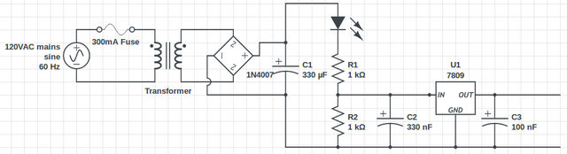
Schematic
Load Test (Load Resistance vs Supply Voltage)
No load -> 9V
100k resistor -> 9.27V
10k resistor -> 9.24V
5k resistor -> 9.16V
2k resistor -> 9.06V
1k resistor -> 8.72V
660 Ohm resistor -> 7.45V, supply voltage started to fluctuate +-40mV
330 Ohm resistor -> 5.45V, supply voltage fluctuated +- 100mV
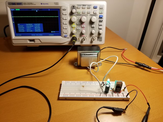
Gallery
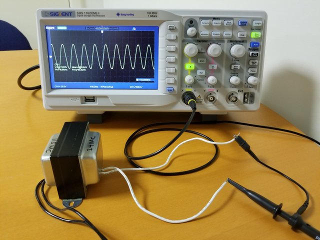
Secondary Voltage
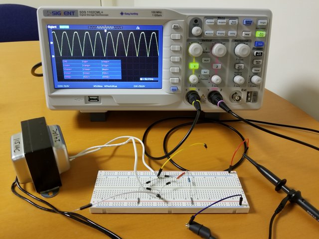
Bridge Rectifier
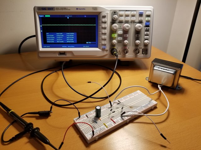
Smoothing Capacitor
Voltage Regulator
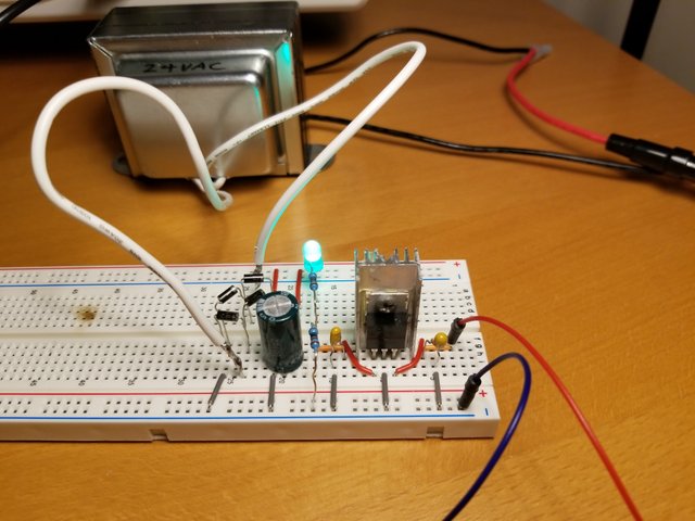
Closer Look
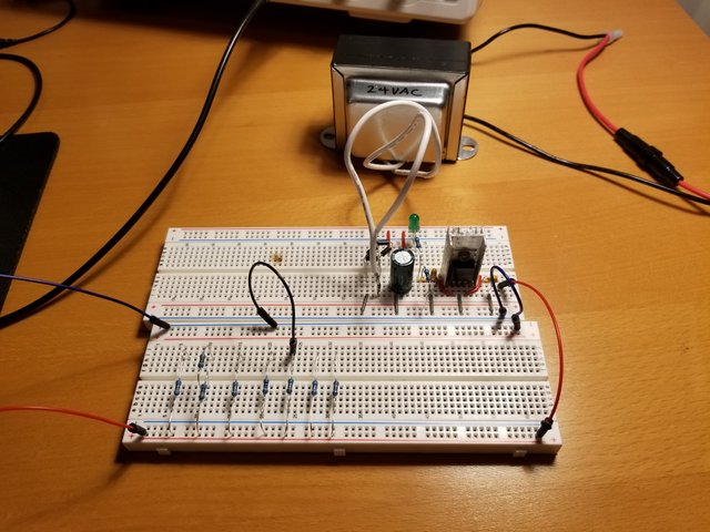
Load Test
Notes
- Calculate voltage rating of circuits using peak voltage, not RMS voltage.
- Placing fuse on the primary side is recommended to protect the entire circuit. Calculate the current rating based on the load. Remember that the current flow increases from primary to secondary.
- Using a transformer naturally offers electrical isolation from the mains voltage. One must be extra careful using oscilloscope probes on grounded circuit.
- Smoothing capacitors significantly increases the RMS voltage near the peak value.
- The voltage divider serve two functions 1) bleeder resistor 2) voltage divider. Bleeder resistor discharges 330uF capacitor for safety when the power is turned off. Voltage divider lowers the input voltage to the regulator since without it the input voltage would be 36V, above the max input voltage rating.
- Use heat sink with the voltage regulator to dissipate heat.
- Supply voltage fluctuates depending on the load. In contrast to ideal voltage source, practical voltage source can only supply finite amount of current. If the load's resistance is low enough to draw higher current than the voltage source can provide, the supply voltage will decrease.
- Power factor of 0.5 demonstrates how inefficient linear power supplies are.
Resources:
Power supply comparison
https://www.acopian.com/linear-power-supply-vs-switching-power-supply-vs-unregulated-power-supply.html
Floating power supply
https://community.keysight.com/community/keysight-blogs/general-electronics-measurement/blog/2016/09/16/what-is-a-floating-power-supply-output
Various options for power supply unit
http://embien.com/blog/embedded-system-design-power-supply-design/
Load transient recovery
http://gpete.blogs.keysight.com/2010/06/what-is-load-transient-recovery.html
Bleeder resistor
https://electronicscoach.com/bleeder-resistor.html