A BETTER APPROACH TO MANAGING SCHOOL ATTENDANCE
About my week. It was hectic. I had to do a project summary for one of my lecturers in school. Sleepless nights and sore back was the reward. It was hectic at first.
The project was restructured and written using the software LATEX. This is the project.
A WIRELESS FINGERPRINT ATTENDANCE MANAGEMENT SYSTEM.
ABSTRACT
The project aims at solving the problems of automated attendance management systems by designing and implementing a wireless fingerprint attendance management system using biometric data capture and ZigBee wireless technology. The system was designed to manage the attendance of students by capturing the fingerprint data of the students and sending these data to a remote location via wireless technology. The computer has a VB.net designed software and a MySQL database to effectively manage records of student and provide a user friendly interface. The project, taking into consideration cost,portability and simplicity, the system was successfully implemented and tests results showed the advantages it had over its traditional counterparts.
INTRODUCTION
Attendance in any organization is very important as it ensures that individuals are present at places they are expected to be and at the time they are expected to be there. In a corporate world, managing attendance is done to minimize losses that may arise from downtime. These organization, by keeping a proper attendance system will be able to achieve better human resource practice system.
Attendance is key to a productive business. If attendance is not properly kept in check, then productivity suffers.
In the education sector, the importance of attendance cannot be over emphasized. In developing nations, a fraction of the attendance is used as a requirement or criterion to allow students sit for exams. Managing the records of the attendance is the attendance management system. The task is very arduous but attendance serves a very key purpose in educational sector:
[1] Technical courses that's consists of experiments, tests and lab works requires complete attendance to class in order for the student to not only grasp the scientific concept hands on but also be eligible for exams.
[2] Lecturers and instructors can use the attendance system to award scores to students who have been regular to class.
[3] it is a pivotal data input to studies that entails finding new ways for an institution to better their tutoring systems and methods.
There are broadly two categories of collection of attendance record in the educational and corporate sector.
[1] conventional method which involves registers, time sheet,and time clock.
[2] automated method which concludes bar codes, magnetic stripes, radio frequency identification (RFID) , and biometric attendance system.
Over the years , there has been several systems designed to provide a better attendance management system but they all had shortcomings. They are as follow:
[i] Time wastage: in the ink and paper method of putting down attendance, the task can be very daunting. Most especially for a large class. Imagine taking attendance for a class population of 800 students on pen and paper.
[ii] Error:Students can intentionally answer names that are not theirs during a roll call. Even lecturers can make error when marking the names of these students or entering the names.
[iii] Complexity: at the end of the session when it comes to analyzing the records of the students, it can be very tasking to carry out proper analysis for a large number of students.
Owing to the problems faced in trying to properly gather attendance records of students, there is the need fora reliable attendance management system.
Aim
The aim of the project is to design a wireless fingerprint attendance management system. The device will he able to:
[i] capture and store prints
[ii] search and match prints
[iii] transfer the matched print to a remote system.
SCOPE
[i] A fingerprint capture circuitry
[ii] implementation and testing
[iii] Analysis of results
[iv] development of a software that uses a database to maintain students records.
TYPE OF ATTENDANCE SYSTEMS
Biometrics is a field in science that deals with the aggregation of biological data to be used for analysis. Biometrics include voice pitch, retina scan, fingerprint etc. The fingerprint is the most common biometric data, and obviously unique to an individual which makes it a viable parameter in identification and security.
Integrating biometrics into attendance management system should be tapered to meet certain standards.
[i] Cost: the cost per unit system should be low
[ii]Power: the system should consume less power. Energy is extensive
[iii] Simplicity: the system must allow for easy large scale production.
[iv] Portable: Devices should be carried easily.
REVIEW OF EXISTING SYSTEMS
In the course of this study, some systems were studied to give the guideline for this particular system.
[1] Embedded Computer Based Lecture Attendance Management System
African Journal of Computing and ICT Vol 4, No.3 , Page 27-30
An electronic card containing user unique identity such as name , matriculation number and a special code. These data are serially interfaced with the port of the computer. The encrypted code and entrance code of the student is compared and attendance is/is not given depending on the outcome of the comparison. It was slow cost but its major drawbacks were risk of impersonation, inability to maintain the RFID card and the process of installing the detectors.
[2] Real-Time Computer Vision Algorithm
ITI 2010 32ND International Conference on Information Technology Interfaces June 21-24,2010, Cavtat, Croatia
The system went a step further by employing facial recognition and computer vision to mark attendance. This eliminated the stress of name calling and use of RFID cards. However, it was ineffective in terms of capturing faces of all the students. Considering the fact that there could be a substantial change in facial structure from time of registration to subsequent verification, it was not a viable solution.
[3] Wireless Attendance Iris Recognition
The system leveraged the Daugman algorithm to identify students by recognizing the retinas in an offline system. The problem of this system is in laying the transmission lines.
[4] Fingerprint Scanner
Fingerprints of students is captured and stored on a personal computer during lectures , tutorials , and practical sessions. It was near effective. The problem with this system is that the computer must be installed in the classroom and it was not a wise decision considering the cases of insecurity.
MATERIALS AND METHODS
[1] Biometrics
The most captivating feature of biometrics is its uniqueness. It is impossible to find another person in the planet with the same fingerprint as you.
The ease of acquiring fingerprint makes the fingerprint the best choice for the project. The prints usually appear as series of dark lines that represents the high, peaking portion of the friction ridge skin while the valleys between these ridges appears as white spaces are the low, shallow portion of the friction ridge skin.
The attendance process with the fingerprint occurs in two stages:
[i] Enrollment: the student places his finger for capture
[ii] Matching: the student's print is then cross referenced with an array of recorded prints.
[2] ZigBee
The ZigBee technology builds devices on the concept of wireless sensor networks (WSNs). WSNs are easily set up(adhoc), low power dissipation, low cost and convenient network systems.
The ZigBee technology built in 2007 comes in two sets:
[i] ZigBee feature set(small network)
[ii] ZigBee feature set pro (larger networks)
The ZigBee system can support up to 64000 devices.
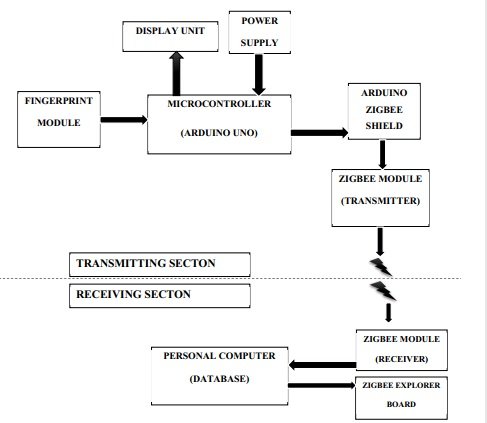
Sections and Components
The system is divided into the transmitting and receiving section. The former handles the data capture, storage, matching and transmission; and the latter is responsible for receiving the data and carry out user defined procedure.
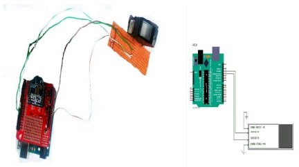
Fingerprint Module:
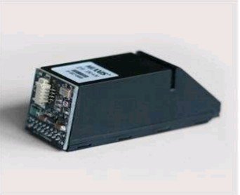
This module is the latest release of the Miaxis Biometrics company. it consists of optical fingerprint sensor, high performance DSP processor and flash. some of its features and specifications are enumerated below:
- Low cost
- Algorithm with better performance
- Easy use and scaling
- Low power consumption
Ratings
- Operating voltage 4.3Volts to 6Volts
- Voltage rating is 6.5Volts
- Fingerprint template 768
- Search time is less than 1.5seconds
- Tolerated offset is 45 degrees
- Power on time is less than 200ms
- User flash memory is 64KB
- Communication Baud rate is 57600bps
Microcontroller:
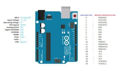
The microcontroller is interfaced with the transmission section of the system and it controls the working of the entire transmission section. The microcontroller is the Arduino Uno.
Arduino is an open source electronic platform creating easy to use hardware and software. The uno board issues commands based on input from the receiving section. The output of every action or process is displayed on the screen of LCD. The board consists of an ATmega 16U2 onboard, built with a firmware like the standard USB drivers. This is good because no external drivers will be required during installation.
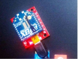
XBee Shield:
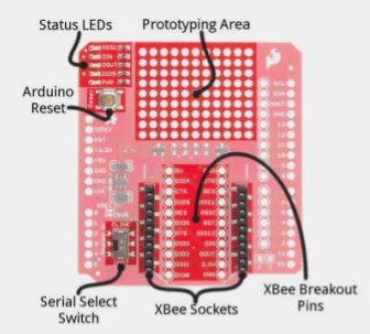
The purpose of the shield is to give extra functionality and provide a smooth interface between ZigBee module and the Arduino Uno. There are two modes of operation which is activated by a single pole double throw (SPDT) switch. This shield also ensures the right amount of voltage is sent to the ZigBee module.
ZigBee Module:
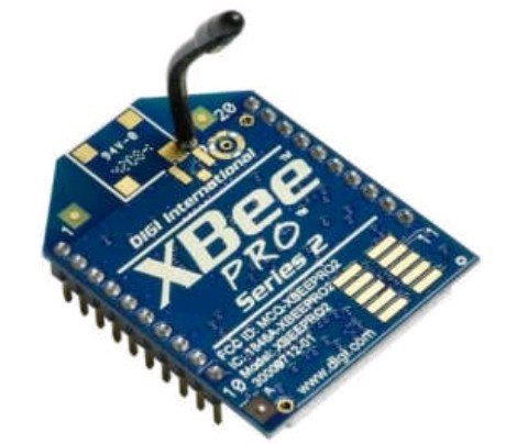
A low cost, low power mesh network standard that provides high reliability and range. The module works in the industrial scientific and medical bands. Transfer bit rate ranges from 20 to 250Kbps.
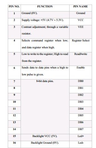
LCD:
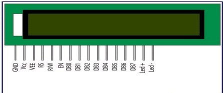
Liquid crystal display is an electronic display module. It is preferred to seven segments because they are economical, easily programmable and displays special characters.
The LCD is 16 X 2, this implies that sixteen characters are displayed per line. The registers in the LCD are the command registers (stores the commands the LCD will perform ) and the data registers (stores the data to be displayed)
Receiver Section
[1] WorkStation:
This is simply the computer where the database record is stored and accessed and modified. Visual Basic is used for the user interface and MySQL is used for database management.
[2] ZigBee Exploration Board:
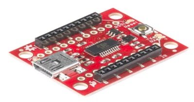
This is the interface between the ZigBee module and the workstation and it is achieved by setting up a virtual communication port via USB. Every data sent and received is done via the USB port. The FT231x USB converter is responsible for translating the information from workstation and the ZigBee module.
The board comes with four light emitting diodes LED that aids debugging. The LED indicates power, transmitting, receiving and Signal Strength (RSSI).
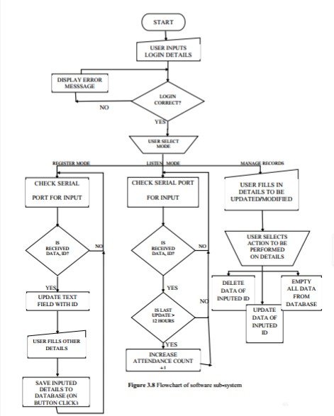
DESIGN METHODOLOGY
The design methodology takes into consideration simplicity, reliability, and component minimization. The graphical representation of how the various units will be interacting is depicted. A flowchart is also designed to represent the algorithm.
[1] Fingerprint Capture Unit:
This unit captures and store a fingerprint template. The module is the SM630 and it is connected to pins 11 and 12 (the digital pins) of the microcontroller. Connecting these pins to function is made possible by installing a software library.
#include <softwareSerial.h>
softwareSerial mySerial(11,12);
Every action carried out by the fingerprint module is controlled by the microcontroller and the data are sent as packets. An example of a code to sent to the controller is as follow:
byte addFingerPrint[ ] = {0x4D,0x58};
mySerial.write(addFingerPrint,sizeof(addFingerPrint));
This sends an array of hex values to the a module to store fingerprint to the identifier location specified.
[2] Power Unit:
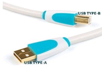
For the purpose of flexibility, the power supply is integrated to an already available power source(USB 2.0 and 3.0). The 5V supply voltage and current of 0.5mA is sufficient to drive the circuit.
[3] Display Unit:
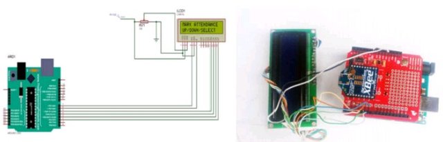
The unit is for display of information. If there is a failed or successful attempt to capture a print at the transmitting section; mismatch of prints, the message is displayed on the screen.
The brightness of the LCD is controlled by applying voltage to pin 3 of the LCD. Voltage brightness relationship is proportional.
The unit is made of data pins that can operate as 4 bits or 8 bits. For this system in concern, the 4 bit mode is used to minimize pin usage.
The LCD pins [4,6,11,12,13,14] are mapped to the controller pins [7,6,5,4,3,2]. The code to initialize these pins are as follow:
#include <stdio.h>
LiquidCrystal lcd(7,6,5,4,3,2);
lcd.begin (16,2);
lcd.setCursor(0,0);
lcd.print("mark attendance ");
[4] Control Unit:
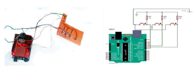
The chip used is the ATMEGA 328 chip. The arduino board is tailored to work easily with the chip. The buttons connected enable user to select what function the system is to perform.
When the microcontroller sends or receive instruction, it does so using s peer to peer network configuration, following the IEEE 802.15.4 standard.
Sending and receiving data is done on the ZigBee module pins 0 and 1of the microcontroller. The pins 0 and 1 are serial pin thus any data written to it is available to the ZigBee module. After initializing the serial port to the band rate, any data written to or from the serial port is sent or received from the ZigBee module respectively.
[5] Software Subsystem:
[i] Designed to work on any PC of window 7 and above
[ii] Manage the database and provide the user interface (UI) for interaction.
[iv] Updating the database with received data.
[iv] Development of the software is achieved using VB.net
[6] Hardware Ciruit Operation:
The functions of the system are as follow:
[6a] Add Fingerprint
Connect the receiving section to the appropriate port.
- "Register Students" is selected on the PC software.
- Navigate to add fingerprint
- Student fills in the required information to be transferred to the PC
- Registration success message is shown to the student
[6b] Mark Attendance
- Connect the receiving section to the appropriate port.
- "Mark Attendance" is selected on the PC software.
- User navigates to mark attendance on the transmitting section.
[6c] Check Print
The user navigates to check print menu on the transmitting section and selects it. The print to be checked is brought up to the screen and cross referenced with a list of prints already in the database.
[6d] Delete Fingerprint
- connect the receiving section to the appropriate port.
- select "MANAGE RECORDS"
- select "DELETE DATA"
place the desire print in the space provided - click the delete button
[6e] Empty Database
- connect the receiving section to the appropriate port.
- select "MANAGE RECORDS"
- select "EMPTY DATABASE"
- User navigates to transmitting section to empty the datatbase.
[7] XBEE CONFIG
[Step 1]
Connect first ZigBee module to the Explora Board.
[Step 2]
Connect the Explora Board to the computer via the USB port.
[Step 3]
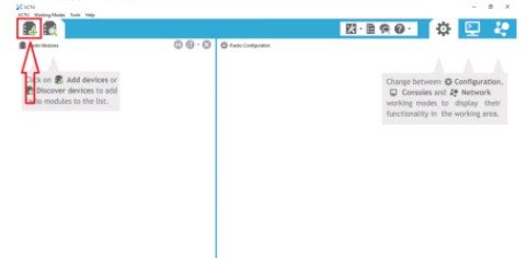
Download the XCTU software and open to reveal user interface.
[Step 4]
Add modules to the software.
[Step 5]
Select from the list of appropriate serial connection. if the module is not found, disconnect and refresh the list.
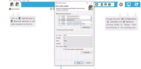
[Step 6]
Add the new connection port to the previous list.
[Step 7]
Select "finish" to load the module data onto the XCTU software.
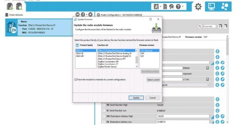
[Step 8]
Setup and update the firmware and the module is configured.
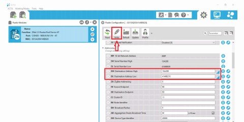
[Step 9]
Area network ID is assigned. the ID range from 0000(hex) to FFFF(hex)
[Step 10]
Click write to burn new settings into the module.
[Step 11]
REPEAT STEPS 1 to 10 for the second ZigBee module. when done you unmount the module.
RESULTS AND CONCLUSIONS
The results after testing the wireless fingerprint attendance management system is recorded below:
[1] System Test 1
Computer Engineering 500 level is used as the case study. Ten students are enrolled for a total of ten classes. The output is as follow:
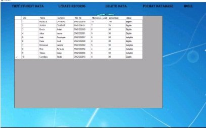
Attendance:this is the number of classes attended by the student.
Percentage: The system computes the percentage of the student obtains.
Status: A status to determine if the student is eligible to sit for the examination.
[2] System Test 2
The efficiency of the system is checked against other traditional systems. the results are presented below
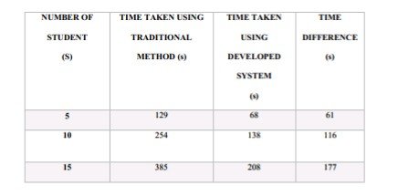
As shown from the table, the advantage of the designed system is made obvious when handling a large number of students.
CONCLUSION
This gives an overview of the whole project. It passes conclusion on the design process and the result being obtained, and limitations encountered during building the system. The end of chapter gives recommendation for future extension to improve functionality.
The project solves the problems of poor efficiency, portability among others by designing and developing and implementing a biometric attendance management system using fingerprint technology and ZigBee wireless technology.
LIMITATIONS
[1] The designed system can be used for only one course at a time.
[2] The maximum distance between receiver and transmitter is 100m. Beyond that distance communication cannot occur.
RECOMMENDATION
[1] A more sophisticated software can be designed to allow system accommodate more courses.
[2] A wireless transmitter that will cover longer distance than the one covered by the ZigBee module.
Great info! The main benefit of attendance software
is it reduces the use of paper an maintain accuracy. Automatic attendance files with the help of biometric attendance machine for student and as well as employees.