Beyond Human Imagination : Transmission Lines
Transmission lines are special cases of electromagnetic waves that deals solemnly with time varying voltage in one of my previous article on steemstem, emphasis was placed on
the subject electromagnetic waves that deals with electric and magnetic fields that varies with time.
Transmission lines are unique because the concept of voltage and current are still very much valid.
In this article, i will still be working with the concept of voltage and current which everyone is familiar with and then gradually introduce concept of space into
the circuit analysis.
Structures of transmission lines
Transmission lines can best be defined as a medium of power transfer from one point to another, this transmission is done through a variety of structures, some of which are explained below;
Co-axial cable
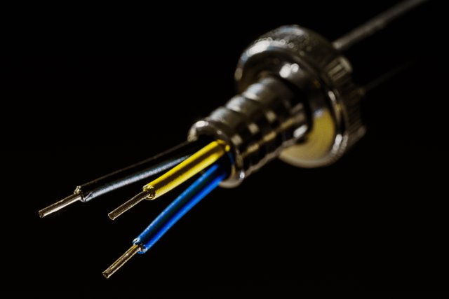
In this particular setup, there’s an inner and outer
conductor and voltage is applied between the inner and outer conductor thus energy will be propagated along the length of the structure.
Parallel wire transmission lines
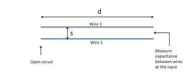
This setup is quite the simplest. We simply have two separate conductors hence when voltage is applied at both end, energy flows.
Microstripline
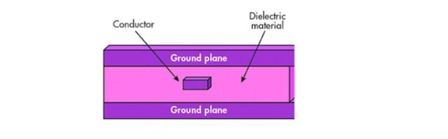
The microstripline is a transmission line geometry with a single conductor trace on one side of a dielectric substrate and a single ground plane on the other side.
Unbalanced
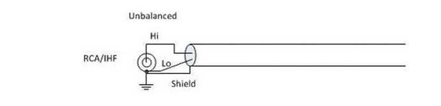
In this structure we have a conducting rod above a
ground surface and voltage is applied between the rod and the ground surface hence power is transmitted efficiently along the structure.
: Stripline
This is also known as differential-stripline. The structure is made up of two parallel conductors enmeshed in a dielectric that has conducting surfaces at the top and the bottom and is grounded while the voltage is applied between the two conductors.
The summary of all we’ve been discussing is that we are having a two conductor system hence when voltage is applied between them, due to the fact that it is a time varying voltage current flows through the system.
All the structures can be represented by a simple two conductor system and this is also done for transmission line analysis where we ignore the structure and simply treat it as two conductor system and at one end we apply energy source and at the other end we apply a load and then carry out analysis from the source to the load.
Concept of transient time effect
Circuit laws like Kirchhoff’s law, are limited to low frequency circuits where we only take note of the value of the electrical components, i.e. For a circuit that comprises of resistors, capacitors and inductors, only their values are needed for the circuit analysis.
However as frequency increases, the signal value changes significantly. A good example is the diagram below;
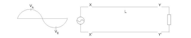
At some instant, VA applied at X, and when L is sufficiently small relative to the length (λ = wavelength). We assume that VA appears at Y from X almost instantaneously. But if F (frequency) of the signal is very high, λ gets very small and so is far less than L, hence VA applied at X takes some finite time before It gets to Y as L >> λ(high frequency). Therefore VY is not always Vx. In transient time effect one can realise that λ approaches L and so it is very likely that Vx not equal to VY, but when λ >> L (for low frequency circuits) the sinusoidal wave changes slowly so that we can assume it is constant across the entire L. The finite time it takes the voltage at X to appear at Y is called transient time.
So when a time varying signal is applied at X, it requires a finite time to travel from X to Y. VA at X will not remain constant as it is a time varying sinusoidal, so that in the transient time it takes VA to appear at Y, VA would have change to another value say VB, so when a voltage at Y is VB say, voltage at X is VA.
In other words, there is a potential difference between X and Y. This difference is related to the length of the cable, the more the length the more the difference, with L very small. Vx is close to VY as the point A and B will be close to beach other and voltage difference will not be substantial. The important thing here is no matter how small thelength we take, there will always be that voltage difference VX–VY = 0 if L → 0
As we increase the frequency, the role of transient time beffect becomes more and more important. So now to the big question; When do you neglect transient time effect and when do you incorporate it in your design?If VX–VY is small, transient time effect can be neglected otherwise it should be taken into consideration.
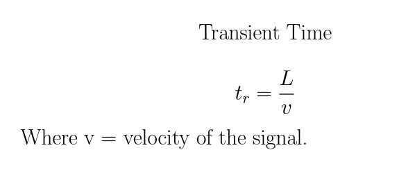
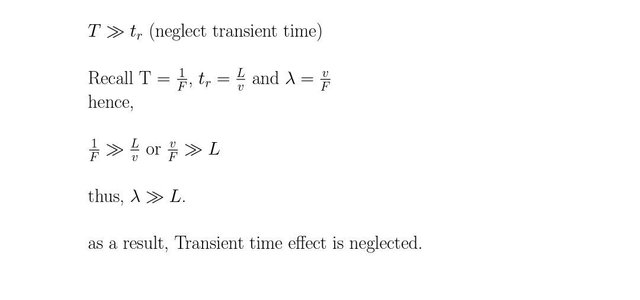
Generally, if tr << T (period of signal) neglect transient time effect but if tr is comparable to T (signal period), then we have to incorporate the effect of transient time in other words, when carrying out circuit analysis, the size of the structures has started playing a role in the analysis.
Analysis of Transmission line
In low frquency analysis, there is just a circuit size that fits all value like saying R= 0.1Ω, L=0.1H and C =
0.1µF, unlike in high frequency where we have 10Ω resistor of 1cm, 10cm and 100cm lengths which will cause each of the circuit to behave differently because of the vnon-uniform length when transient time effect is considered.
However, we still want to use our basic laws that we are familiar with for low frequency. The approach of this law will break the LUMPED ELEMENT into DISTRIBUTED ELEMENT and also have per unit element value for each of the element. The division of
each circuit element in space is done in such a way that L is infinitisimally small so that the circuit laws at low frequency can apply within two nodes created by the division
Transient time cannot be neglected for a two conductor wire but when small quantity in length is broken down into very Lineal element of ∆x with ∆x → 0, then the transient can be neglected as L >> ∆x and so the circuit laws of low frequency can be applied to the abitrary nodes separated by ∆x length. In the circuit, we should have resistance, capacitance and inductance stated in total value, instead we have resistance, inductance and capacitance all per unit length. The relationship between voltage and current is valid for high frequency like that of low frequency as ∆x → 0 (infinitisimally small).
Hence, this solves for voltage and current of a transmission line in the presence of transient time effect.
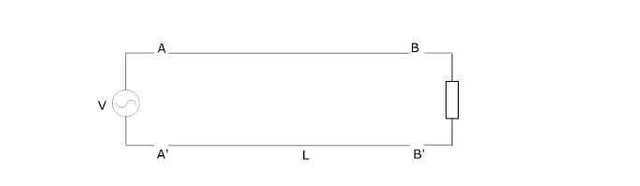
In the circuit above, there is a voltage difference between both ends because of transient time effect but we do not know why there is a voltage difference.
NOTE: ALL IMAGES WITH NO SOURCE ARE ORIGINAL
Reference
1. Jackman, Shawn M.; Matt Swartz; Marcus Burton; Thomas W. Head (2011).
2. Oklobdzija, Vojin G.; Ram K. Krishnamurthy (2006). High-Performance Energy-Efficient Microprocessor Design. Springer Science & Business Media. p. 297.
3.Guru, Bhag Singh; Hüseyin R. Hızıroğlu (2004). Electromagnetic Field Theory Fundamentals, 2nd Ed. Cambridge Univ. Press. pp. 422–423
4.Schmitt, Ron Schmitt (2002). Electromagnetics Explained: A Handbook for Wireless/ RF, EMC, and High-Speed Electronics
5.Carr, Joseph J. (1997). Microwave & Wireless Communications Technology
6.Journal of Magnetic Resonance – Impedance matching with an adjustable segmented transmission line". Journal of Magnetic Resonance.
7. Syed V. Ahamed, Victor B. Lawrence, Design and engineering of intelligent communication systems, pp.130–131, Springer,
8. Naredo, J. L.; Soudack, A. C.; Marti, J. R. (Jan 1995), "Simulation of transients on transmission lines with corona via the method of characteristics", IEE Proceedings. Generation, Transmission and Distribution., Morelos: Institution of Electrical Engineers,
9. My lecture note

With the major objective of steemSTEM to advance Science, Technology, Engineering and Mathematics on the Steem blockchain. In the event that you wish to help the steemSTEM to promote their major objectives, which can be done by contributing on STEM content and using the tag #steemstem , also support steemstem creators ,join the curation trail and you can also delegate SP to steemstem.
it's good to see something of this sort coming to play. Thanks for sharing, it is enlightening.
it's my pleasure sir and thanks for coming around.
Congratulations! this post got an upvote by @steemrepo and was manually picked by the curator @yandot to be added on STEEM REPOSITORY, simply comment "YES" and we upload it on STEEM REPO Website.
Want to know more about the Steem Repo project? Contact us on Discord
YES