Basic electricity / The Capacitor
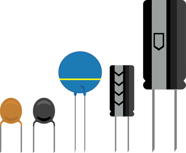
The physical shape of the different capacitor. Pixabay

The capacity of the element is the property of storing electrical charges when subjected to a voltage and is given by the formula C=Q/V Where
C: Capacity in Faradian (F)
Q: Load stored in Columbus
V: Electrical voltage
The capacitors have small capacities with respect to their basic magnitude, being the largest of them in millifarads (mF)=0.001F or 10E-3F, up to picofarads (pF)=0.0000000000000001F or 10E-12F.
To determine the energy stored in a capacitor, it is sufficient to take into account its capacity and the voltage at which it is supplied. For which we can use the formula E=C x V2/2
Capacitor structure
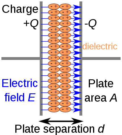
Capacitor structure commons.wikimedia
A dielectric is a non-conductive material (already described in previous articles) which means that it does not allow the charges that reach the capacitor to pass through it; but when the capacitor is charged, an electric field is generated by the storage of charges in its plates, this causes the dielectric, since its molecules are polarized, to be oriented in the form of dipoles so that the negative pole is attracted by the positively charged plate and vice versa. In ideal conditions we can say that the plate plates are filled with positive and negative charges respectively, until reaching the same potential of the source. If the voltage of the source drops, the capacitor gives up its loads until the voltage is equalised, thus making the field external and internal electrical power are matched.
Temperature coefficient
These components as well as others are affected by the temperature which makes their capacities decrease, the effect of the temperature will depend on the composition of the dielectric as I mentioned above, I have taken the dedication to make a table for you, (I want my items to be well presentable)
Capacitor voltage
Capacitors cannot be subjected to any voltage level, the maximum values must be known to avoid destroying the component, capacitors can generally be subjected to three types of voltages:
Test voltage, usually double or triple the voltage at which the capacitor will normally work (without exceeding the maximum voltage indicated by the manufacturer), is used to check the characteristics of the insulators.
Working voltage, is the maximum voltage at which the capacitor can be permanently operated without deteriorating.
Peak voltage, is the maximum voltage that can be operated for short intervals of time, usually in minutes per hour of operation.
I have decided to create a table to share with you the voltages of the capacitors based on the type of capacitor, even so, I recommend always to verify with the manufacturer's instructions.
Charging and discharging a capacitor
As I said before, the charge and discharge of a capacitor will depend on the capacitor capacity, the resistance used for this purpose and the voltage applied. In ideal conditions the capacitor will always try to charge at the same value of the voltage source, for a practical demonstration I will use the livewire simulator, in it I will simulate the charge and discharge so we can see it graphically.
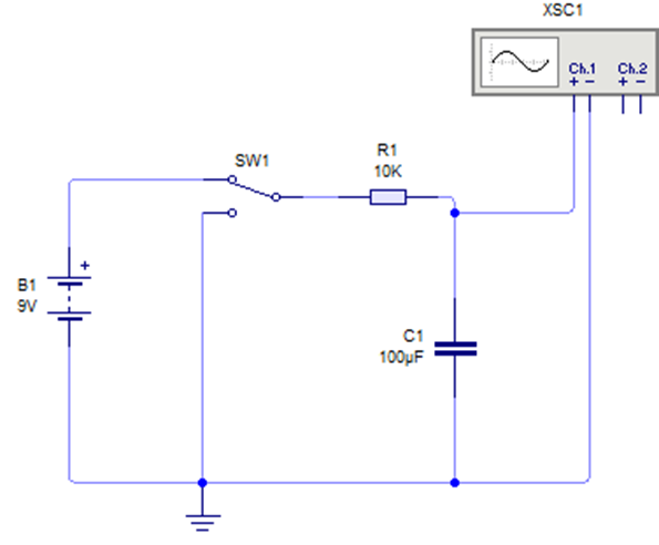
Circuit to illustrate the charging and discharging of a capacitor, with the support of the virtual oscilloscope to visualize the corresponding graph. Image created by the author using the livewire simulator
We can see in the circuit that the circuit breaker is positioned to energize the capacitor, I have chosen a high value for the resistance in order to increase the charging time, this way we will have a better appreciation. With the support of the virtual oscilloscope provided by the simulator, we can visualize the load graph.
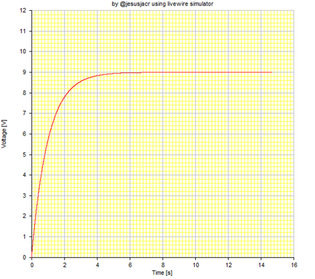
Voltage/time graph to illustrate the charging of a capacitor. Image created by the author using the livewire simulator
When the voltage in the capacitor reaches the value of the battery voltage, they remain at the same potential, and current stops flowing. One thing we can notice immediately is that the load curve is exponential. If we want to calculate the value of the load stored by the capacitor in an instant we can apply the formula Q = CV(1-e-t/RC). In real conditions, the capacitor is never fully charged due to the existing pressure drop. Theoretically, we can consider that it has been charged when a time (t) has elapsed, which is determined by the following formula t = 5RC, note that the R and C variables are the ones that can manipulate this time, in the future we will use this to create timers.
We can consider the charging time equal to the discharge time, if we change the positioner switch we can notice the discharge graph of the capacitor.
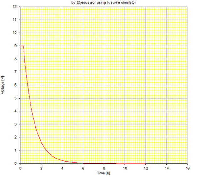
Voltage/time graph to illustrate the discharging of a capacitor. Image created by the author using the livewire simulator
Applications
An important thing to note is that the capacitor behaves like an open circuit when direct current is applied to it, and if it is alternating it acts as a closed circuit creating an impedance related to the frequency of that current, which allows the passage of current in one direction only, this property is used for filtering alternating current.
CAUTION: Never do anything with electricity that you're not sure of, it's easier and less trouble to ask someone who understands.
Other recommended readings
Mulukutla S. Sarma. Introduction to Electrical Engineering
New York Oxford
OXFORD UNIVERSITY PRESS
2001
If you love science, technology, engineering or mathematics I invite you to learn more about the @steemstem team by entering the channel at discord here, You can also find more information about the equipment and even valuable tips I recommend you read to improve your publications here.
I hope you found this publication useful. My intention is that we can know the essential components and then create circuits that can be useful to us. Thank you once again for reading, I bid you farewell wishing God to give you wisdom and bless all your projects according to his will for your well-being.
I find this one to be a good article.
I remember @fona and his nice articles, he wrote something similar a while ago.
Don't worry about being noticed, good articles are noticed eventually, as I told you in Discord :P
Keep writing and don't forget to also interact with other authors, they can cast votes too if they see you as an intelligent and considerate person.
Cheers!
They definitely didn't find this one, my friend! :)
Thank you very much for the comment, these are very useful tips that help us to grow, I particularly take them into account because they are being very helpful to me to improve on the platform.!
Cheers!
excellent classes of those electric circuits, the capacitor and its operation and structure .
thank you so much!!