Blinkit v2.4: Arduino integration | Chose your effect !
Blinkit v2.4: Arduino integration | Chose your effect !

After having tested out many times and used Blinkit with Arduino a lot, we started to feel we needed to expand and give to users more choices (eventhough users can find it funny to only blink a led or change the speed and the number of blinks). This is why we decided to implement some effects to be assigned for each notification to let Blinkit become even more an interactive and funny platform to receive Steem related notifications.
Arduino standby light breathing and light effects on notifications
After several testing of our last release of the RGB led mode with the light effect during booting of Arduino we have pointed out that, having only a booting light pattern during Arduino start-up phase is surely nice but will not give the right spirit to it as would do a standby "breathing like effect". More over we wanted to make it more interactive, funny and nice looking. This is why we also implemented new light effects to be assigned for each notification. Now the effects that can be chosen are: Normal Blink, Fading, Rainbow, Ice and Fire (more to come soon...).
What is Blinkit?
Blinkit is a notification software that can be used to give to regular and widely available devices a Steem purpose.

Supported devices:
- USB Sticks (status light)
- Philips HUE lamps
- Sonoff devices
- Arduino Boards or compatible (Genuino, etc...)
- Camera status LED blink
- Take photos on upvote/post/follow
- Logitech RGB/Backlight Keyboards (new)
Blinkit can look for new Steem account Upvotes and Followers, and it can notify on new Posts made by a user.
More devices will be added in the near future.
Blinkit is free and open source, and can be downloaded from the Blinkit Github page:
https://github.com/techtek/Blinkit
For more information about the new version of Blinkit please visit the following link

COMPATIBILITY
Current release has been tested only on an Arduino UNO board. Other boards like Mega and Nano should be supported (for Nano different PWM pins should be selected, for Mega nothing to change) but have not been tested yet. Users interested in using this new feature with other boards could submit a test contribution and let us know the result of their test.
New Coded Features:
- Light fading pattern (breathing) during Arduino standby period (while no notifications or no changes in settings)
- New light effects for incoming notifications (fade, ice, fire, rainbow)
With this release our main concerns were:
- How to let users using single leds and/or RGB led have some interactive and more funny effects to chose instead of the standard blinking ?
- How to make sure that connections are well established always?
- How to make sure that wiring had been made correctly ?
- How to give some liveliness to the Blinkit related Arduino boards notifiying users that the board is ready to accept new incoming triggers and/or is waiting for new triggers ??
After some brainstorming with @techtek we decided to let that custom made booting light pattern for Blinkit become a "BREATHING" effect which will fade the RGB led between the main colours of Blinkit's style: Violet and White. This pattern will be triggered and gets repeated forever whenever the board is in standby (no notifications and no changes in settings). Whenever there is a change (so serial is being received) this pattern stops (it stop breathing !!) and process the info received. Then if nothing is there for few seconds it goes back to breathing waiting for new incoming data.
Cencerning the effects, now users can chose from the Blinkit interface which effect to be assigned for each notification.
In 3x Single led mode the effects available for now are: Normal Blink, Fading.
In RGB led mode the available effect are: Normal Blink, Fading, Rainbow, Ice, Fire
More effects to be added soon and more features...
Hereafter i will explain the whole process behind the coding and will explain how the code works to let it work as desired.

How is it implemented?
New parts have been added to the code with a new approach in handling part of the data. A new section (a new function) in the code has been added which is the breath() function that will be responsible to do the breathing while the board is in standby.
The main code structure and interaction is still divided in 6 main parts:
- Declare/set the variables, the arrays etc
- Initializing the setups (Serial Comunication and Output pins)
- Receive serial data to be processed
- Receive serial data and split it in tokens declaring the functions that will handle such data
- Read splitted data and based on some marker store them in the right setting array
- Wait for triggers (upvote, follower, post) over serial and activate the led with one of the chosen effects
Hereafter i will show and explain only the parts of the code where changements have been made.
1) Declare/set the variables, the arrays etc...
char buffer[22];

int RedPIN = 3; //pin for led 1 (single colour led) or pin for the Red led in the RGB led
int GreenPIN = 5; //pin for led 2 (single colour led) or pin for the Green led in the RGB led
int BluePIN = 6 ; //pin for led 3 (single colour led) or pin for the Blue led in the RGB led
//above pins must be DIGITAL PWM PINS (in Arduino Uno, PIN 3, 5, 6, 9, 10, 11 are PWM) in order to obtain the colours shades with the RGB led
int y=0;
int transferdata[3]; //array to be used to store the incoming settings and transfer them to the right setting array
int ledmode[2]; //this array will store the information regarding the ledmode (mode 1 for 3x single colour leds and mode 2 for 1x RGB led )
int blinkdelay[3]; //this array will store the information to be used for the blink speed (in this case it is a delay between blinks)
int Nofblinks[3]; //this array will store the information to be used for the number of triggers/blinks to do (number of repeated triggers)
int BRIGHTU[3]; // This array will store the information regarding the colour of the RGB led for an incoming upvote trigger (3 values for the colour)
int BRIGHTF[3];// This array will store the information regarding the colour of the RGB led for an incoming follower trigger (3 values for the colour)
int BRIGHTP[3]; // This array will store the information regarding the colour of the RGB led for an incoming post trigger (3 values for the colour)
int EFFECT[3]; // This array will store the information regarding the effect chosen for each led/notification (1 for normal Blink, 2 for Fading, 3 for rainbow, 4 for ice, 5 for fire)
unsigned long StartTime; //will be used to calculate timing for fading effect
unsigned long CurrentTime; //will be used to calculate timing for fading effect
As we can see we have introduced a new array, named EFFECT[ ], which will store the information regarding the effect chosen for each led/notification (1 for Normal Blink, 2 for Fading, 3 for rainbow, 4 for ice, 5 for fire). New variables have been added as StartTime and CurrentTime which for now will only be used to calculate time and period for the fading effect but will be used even more in next planned updates.
3) Receive serial data to be processed
void loop(){ //collecting the incoming data and filling the buffer with it
  StartTime = millis(); // updating time
  if (Serial.available() > 0) { //if there is any incoming serial data of any sort (any setting or any notification)
       int index=0;
       delay(100); // let the buffer fill up
       int numChar = Serial.available();
    if (numChar>22) {
       numChar=22;
       }
     while (numChar--) {
        buffer[index++] = Serial.read(); //read serial data and put them in the buffer
        }
        splitString(buffer);
   }
 if (Serial.available() == NULL){    //
   for (int r=1; r<=3; r++){          // if within 3 seconds
      if (Serial.available() == NULL){  // no serial data is detected
        delay (1000);                    //(thus no settings or no notification) -> activate the function breath
       }
      else{ // if serial data is detected then stop the process
        break;
        }}

     breath(); // activate the function called breath (standby fading light pattern)
     }
}
In this main loop Arduino will listen to the COM port and wait for incoming serial data. In this loop we have put the initiation of our breath() function that will be responsible for the fading pattern during standby period. In fact, if no data is detected within 3 seconds Arduino enters the standby mode and start with the fading pattern. At any moment, as you will see in the next part of the code, if any data is being received over serial (new notifications or new settings) the pattern will stop and Arduino will process the incoming data.
However a very important part has been added to the loop. In fact, we called at the very beginning millis(), which is a function integrated in Arduino boards (thus dont need to declare or define it). When called it returns the number of milliseconds since the Arduino board began running the current program. This call for millis() will be useful later when using the fade effect as it will keep track of the timing for the period of fade and other aspects which will be seen later.
4) Breathing function during standby
void breath(){
   int redIntensity = 0;   //variable to handle the brightness of the RED colour of the RGB led
   int blueIntensity = 0;  //variable to handle the brightness of the BLUE colour of the RGB led
   int greenIntensity = 0; //variable to handle the brightness of the GREEN colour of the RGB led

while (Serial.available() == NULL){ //run below fading pattern till some data is detected over serial

 for (int i = 0; i <=240; i+=1){ //This loop will light up/dim linearly the led till it goes from off state to a value close to
                                 //R=110 G=0 B=255 the starting value for our fading pattern

    if (Serial.available() > 0){ //
      analogWrite(RedPIN, 0);    //turn off the led when data is received and exit the loop
      analogWrite(GreenPIN, 0); //
      analogWrite(BluePIN, 0); //
      break;
      }

   redIntensity = i/2;
   blueIntensity = i ;

      analogWrite(RedPIN, redIntensity);     //
      analogWrite(GreenPIN, greenIntensity);  //activate with proper delay the led using the currently stored values for R G B
      analogWrite(BluePIN, blueIntensity);   //
      delay(10);
      }

 for (int t = 0; t<1; t++){  //this FOR loop will let use repeat the below (whole) fade-in, fade-out pattern twice

   if (Serial.available() > 0){ //
      analogWrite(RedPIN, 0);    //turn off the led when data is received and exit the loop
      analogWrite(GreenPIN, 0); //
      analogWrite(BluePIN, 0); //
      break;
      }

 for (int i = 110; i <=255; i+=1){    //In this for loop we will handle the first transition from R=110 G=0 B=255 (darker Violet) to
                                      //R=255 G=10 B=255 (much brighter Violet) and have chosen to use the redIntensity as the variable part of the FOR loop
                                      //based on the value of R = i we will calculate the Green brightness.
   if (Serial.available() > 0){ //
      analogWrite(RedPIN, 0);    //turn off the led when data is received and exit the loop
      analogWrite(GreenPIN, 0); //
      analogWrite(BluePIN, 0); //
      break;
      }

 redIntensity = i;
 greenIntensity = ((118937/10000)*log(i)-(559050/10000)); //The neperien logarithmic function usually wrote as ln(x)
                                                          //is not recognized in Arduino coding by using ln but log

if(greenIntensity> 10){ //based on the aproximation in calculations we do this just in case not to pass the value
  greenIntensity =10;
}
if(greenIntensity< 1){ //based on the aproximation in the calculations this serves to not let
  greenIntensity =0;   //the Green pin turns negative
}

analogWrite(RedPIN, redIntensity);     //
analogWrite(GreenPIN, greenIntensity); //activate with proper delay the led using the currently stored values for R G B
analogWrite(BluePIN, blueIntensity);   //
delay(10);                             //
}

for (int i = 10; i <=220; i+=1){ //using this For loop we handle the linear transition between the bright Violet (R=255 G=10 B=255)
                                 //and the White colour (R=255 G=255 b=255)

   if (Serial.available() > 0){ //
      analogWrite(RedPIN, 0);    //turn off the led when data is received and exit the loop
      analogWrite(GreenPIN, 0); //
      analogWrite(BluePIN, 0); //
      break;
      }

   redIntensity=255;
   blueIntensity=255;
   greenIntensity=i;

analogWrite(RedPIN, redIntensity);     //
analogWrite(GreenPIN, greenIntensity); //activate with proper delay the led using the currently stored values for R G B
analogWrite(BluePIN, blueIntensity);   //
delay(10);                             //
}

//below we reverse the loops used before to fade from Violet to White and use them to do the other way (from White to Violet)
for (int i = 220; i >=10; i-=1){ //using this For loop we handle the linear transition between the White colour (R=255 G=255 b=255)
                                 //and the bright Violet (R=255 G=10 B=255)

  if (Serial.available() > 0){ //
      analogWrite(RedPIN, 0);    //turn off the led when data is received and exit the loop
      analogWrite(GreenPIN, 0); //
      analogWrite(BluePIN, 0); //
      break;
      }

   redIntensity=255;
   blueIntensity=255;
   greenIntensity=i;

analogWrite(RedPIN, redIntensity);     //
analogWrite(GreenPIN, greenIntensity); //activate with proper delay the led using the currently stored values for R G B
analogWrite(BluePIN, blueIntensity);   //
delay(10);                             //
}

for (int i = 255; i >=110; i-=1){ //In this for loop we will handle the transition from R=255 G=10 B=255 (much brighter Violet) to
                                  // R=110 G=0 B=255 (darker Violet) and as before have chosen to use the redIntensity as the variable part of the FOR loop
                                  //based on the value of R = i we will calculate the Green brightness.
   if (Serial.available() > 0){ //
      analogWrite(RedPIN, 0);    //turn off the led when data is received and exit the loop
      analogWrite(GreenPIN, 0); //
      analogWrite(BluePIN, 0); //
      break;
      }

redIntensity = i;
greenIntensity = ((118937/10000)*log(i)-(559050/10000));

if(greenIntensity<1){ //based ont he aproximations this will keep us on the safe side.
  greenIntensity =0;
  }
analogWrite(RedPIN, redIntensity);     //
analogWrite(GreenPIN, greenIntensity); //activate with proper delay the led using the currently stored values for R G B
analogWrite(BluePIN, blueIntensity);   //
delay(10);                             //
}}

for (int i = 255; i >=0; i-=1){ //This loop will dim linearly the led till it goes totally of
                                //since we went back to R=110 G=0 B=255 with a quick calculation and a good aproximation
                                //we set the step to take for each brightness decrease so that they get dimmed simultaneously and of the same ammount each time

   if (Serial.available() > 0){ //
      analogWrite(RedPIN, 0);    //turn off the led when data is received and exit the loop
      analogWrite(GreenPIN, 0); //
      analogWrite(BluePIN, 0); //
      break;
      }

redIntensity = i/3;
blueIntensity = i ;

analogWrite(RedPIN, redIntensity);     //
analogWrite(GreenPIN, greenIntensity); //activate with proper delay the led using the currently stored values for R G B
analogWrite(BluePIN, blueIntensity);   //
delay(10);
}
}
}
Once Arduino will enter the standby mode thus trigger breath() function, this function will continuously loop while no serial data is detected and fade the led between Violet and White (the main colours of Blinkit). As seen in the commented parts of the code, we can see that this light effect, occurring after the WHILE loop, is devided in 5 main parts in the following order:
- Initial FOR loop to do the fading from fully off to R=110 G=0 B=255 which will be the initial colour from which the fading to white will start
- a FOR loop to repeat the whole fading pattern several times
- 2 consecutive FOR loops to do the fading from Violet to White as advised above in the study of the mathematical model
- 2 consecutive FOR loops to do the reverse fading effect (from White to Violet)
- 1 final FOR loop to slowly turn off/slowly dim the led from Violet to fully off
5) Read splitted data and based on some marker store them in the right setting array
void setallsettings(char* data) {

[...]
if (data[0] == 'E') {  //if incoming data has marker "E" store in an array called EFFECT the effect chosen for each notification
        int blinkdata = strtol(data+1, NULL, 10);
        blinkdata = constrain(blinkdata,1,5);
        transferdata[y] = blinkdata;
        y=y+1;
  if (y==3){                                                // when transferdata is full of data (we expect 3 values, one for each notification)
        memcpy(EFFECT, transferdata, sizeof(transferdata));   //copying transferdata to EFFECT then clearing transferdata and resetting y,
    for (int i=0; i<=sizeof(transferdata); i++){
        transferdata[i]= '\0';
        }
      y=0;
   }
}

if (data[0] == '?'){   //send command set to view on serial all the current setups
      Serial.println("Current Settings: ");
      Serial.println("---------------------------------------------------- ");
      Serial.println(" ");
if(ledmode[0]== 1){
        Serial.println("ledmode is set to: 3x single colour LED ");
        Serial.println(" ");

    for (int i=0;i<=2;i++){
        Serial.print("effect for led ");
        Serial.print(i+1);
        Serial.print(" is set to: ");
      if(EFFECT[i]==1){
        Serial.println("NORMAL BLINK");
        }
      if(EFFECT[i]==2){
        Serial.println("FADING");
        }
      }
      Serial.println(" ");

  for (int i=0;i<=2;i++){
      Serial.print("Nofblinks for led");
      Serial.print(i+1);
      Serial.print(" is:");
      Serial.print(Nofblinks[i]);
      Serial.println(" Blinks");
    if (i==2){
      Serial.println(" ");
      }
   }
  for (int i=0;i<=2;i++){
        Serial.print("blinkdelay for led ");
        Serial.print(i+1);
        Serial.print(" is:");
        Serial.print(blinkdelay[i]);
        Serial.println(" Millis");
     if (i==2){
        Serial.println(" ");
        }
   }
}
   if(ledmode[0]==2){
              Serial.println("ledmode is set to: 1x RGB LED ");
              Serial.println(" ");

              Serial.print("number of blinks for upvote trigger is: ");
              Serial.print(Nofblinks[0]);
              Serial.println(" Blinks");
              Serial.print("number of blinks for follower trigger is: ");
              Serial.print(Nofblinks[1]);
              Serial.println(" Blinks");
              Serial.print("number of blinks for post trigger is: ");
              Serial.print(Nofblinks[2]);
              Serial.println(" Blinks");
              Serial.println(" ");

              Serial.print("blinkdelay for upvote trigger is: ");
              Serial.print(blinkdelay[0]);
              Serial.println(" Millis");
              Serial.print("blinkdelay for follower trigger is: ");
              Serial.print(blinkdelay[1]);
              Serial.println(" Millis");
              Serial.print("blinkdelay for post trigger is: ");
              Serial.print(blinkdelay[2]);
              Serial.println(" Millis");
              Serial.println(" ");

              Serial.println("RGB value for upvote trigger is set to");
              Serial.println(" ");
              Serial.print("R= ");
              Serial.println(BRIGHTU[0]);
              Serial.print("G= ");
              Serial.println(BRIGHTU[1]);
              Serial.print("B= ");
              Serial.println(BRIGHTU[2]);
              Serial.println("");

              if (EFFECT[0]==1){
                Serial.println("Effect for upvote is: NORMAL BLINKING");
                Serial.println(" ");
                 }
              if (EFFECT[0]==2){
                Serial.println("Effect for upvote is: FADING");
                Serial.println(" ");
                 }
              if (EFFECT[0]==3){
                Serial.println("Effect for upvote is: RAINBOW");
                Serial.println(" ");
              }
              if (EFFECT[0]==4){
                Serial.println("Effect for upvote is: ICE");
                Serial.println(" ");
              }
              if (EFFECT[0]==4){
                Serial.println("Effect for upvote is: FIRE");
                Serial.println(" ");
              }

              Serial.println("RGB value for follower trigger is set to");
              Serial.println(" ");
              Serial.print("R= ");
              Serial.println(BRIGHTF[0]);
              Serial.print("G= ");
              Serial.println(BRIGHTF[1]);
              Serial.print("B= ");
              Serial.println(BRIGHTF[2]);
              Serial.println("");
              if (EFFECT[1]==1){
                Serial.println("Effect for follower is: NORMAL BLINKING");
                Serial.println(" ");
                 }
              if (EFFECT[1]==2){
                Serial.println("Effect for follower is: FADING");
                Serial.println(" ");
                 }
              if (EFFECT[1]==3){
                Serial.println("Effect for follower is: RAINBOW");
                Serial.println(" ");
              }
              if (EFFECT[1]==4){
                Serial.println("Effect for follower is: ICE");
                Serial.println(" ");
              }
              if (EFFECT[1]==5){
                Serial.println("Effect for follower is: FIRE");
                Serial.println(" ");
              }

              Serial.println("RGB value for post trigger is set to");
              Serial.println(" ");
              Serial.print("R= ");
              Serial.println(BRIGHTP[0]);
              Serial.print("G= ");
              Serial.println(BRIGHTP[1]);
              Serial.print("B= ");
              Serial.println(BRIGHTP[2]);
              Serial.println("");
              if (EFFECT[2]==1){
                Serial.println("Effect for post is: NORMAL BLINKING");
                Serial.println(" ");
                }
              if (EFFECT[2]==2){
                Serial.println("Effect for post is: FADING");
                Serial.println(" ");
               }
              if (EFFECT[2]==3){
                Serial.println("Effect for post is: RAINBOW");
                Serial.println(" ");
              }
              if (EFFECT[2]==4){
                Serial.println("Effect for post is: ICE");
                Serial.println(" ");
              }
              if (EFFECT[2]==5){
                Serial.println("Effect for post is: FIRE");
                Serial.println(" ");
              }
         }
    }
}
in this part of the sketch we have added the code that will handle the parsing and assignment of the settings for the effect selection made through the interface and have added to the serial feedback lines that will print also the effect chosen for each led.
6) Wait for trigger over serial and activate the realtive LED
void setLEDon(char* data) {
  //if Arduino receives the command u from serial (upvote detected)
if (data[0] == 'u') {
   if(ledmode[0]==1){ //if ledmode is set to 3 single colour led mode
       if (EFFECT[0]== 1){ // if the effect selected is normal blinking
           for (int a= 0; a< Nofblinks[0]; a++){ //repeat the blinking effect as per the Nofblinks[0] value
                if (Serial.available() > 0){ //
                    analogWrite(RedPIN, 0);    //turn off the led whenever data is received and exit the loop
                    analogWrite(GreenPIN, 0); //
                    analogWrite(BluePIN, 0); //
                    break;
                    }
              //do the blinking
                 analogWrite(RedPIN, 255); //turn on the led
                 delay(blinkdelay[0]);
                 analogWrite(RedPIN, 0);//turn off the led
                 delay(blinkdelay[0]);
             }
       }
    if (EFFECT[0]== 2){ // if the effect selected is fading effect
         for (int a= 0; a< Nofblinks[0]; a++){ //repeat the fading effect as per the Nofblinks[0] value
              for (int f=0; f<=255; f++){

                 if (Serial.available() > 0){ //
                    analogWrite(RedPIN, 0);    //turn off the led when data is received and exit the loop
                    analogWrite(GreenPIN, 0); //
                    analogWrite(BluePIN, 0); //
                    break;
                   }

           /////////////////////////////////////////
           // led will fade in from 0% brightness //
           //       to 100% brightness            //
           /////////////////////////////////////////

                   analogWrite(RedPIN, f); // activate the led
                   delay((blinkdelay[0]/20));
              }
           for (int f=255; f>=0; f--){

                if (Serial.available() > 0){ //
                    analogWrite(RedPIN, 0);    //turn off the led whenever data is received and exit the loop
                    analogWrite(GreenPIN, 0); //
                    analogWrite(BluePIN, 0); //
                    break;
                    }

            ///////////////////////////////////////////
            // led will fade in from 100% brightness //
            //      0% brightness back and forth     //
            ///////////////////////////////////////////

               analogWrite(RedPIN, f); // activate the led
               delay((blinkdelay[0]/20));
            }
        }
    }
 }

 if(ledmode[0]==2){
    if (EFFECT[0]== 1){ // if the effect selected is normal blinking
        for (int a= 0; a< Nofblinks[0]; a++){ //repeat the blinking effect as per the Nofblinks[0] value
             if (Serial.available() > 0){ //
                 analogWrite(RedPIN, 0);    //turn off the led whenever data is received and exit the loop
                 analogWrite(GreenPIN, 0); //
                 analogWrite(BluePIN, 0); //
                 break;
                 }
           //do the blinking
           analogWrite(RedPIN, BRIGHTU[0]);
           analogWrite(GreenPIN, BRIGHTU[1]); //turn on the led using the stored R G B values
           analogWrite(BluePIN, BRIGHTU[2]);
           delay(blinkdelay[0]);
           analogWrite(RedPIN, 0);
           analogWrite(GreenPIN, 0);//turn of the led
           analogWrite(BluePIN, 0);
           delay(blinkdelay[0]);
          }
       }
    if (EFFECT[0]== 2){ // if the effect selected is fading effect
       unsigned int PERIOD = (blinkdelay[0]*10);
       double OMEGA = 2*PI/PERIOD; //use a double variable since OMEGA can contain decimals
       int count=1;// variable to count the number of oscillations
       StartTime= millis();

      while (count <= Nofblinks[0]){ //loop to be used to repeat the pattern as per Nofblinks[0] value
               if (Serial.available() > 0){ ///////////////////////////////////////
                 analogWrite(RedPIN, 0);    //turn off the led when any new data //
                 analogWrite(GreenPIN, 0);  //  is received and exit the loop    //
                 analogWrite(BluePIN, 0);   ///////////////////////////////////////
                 break;
                 }

                CurrentTime= millis();
               /////////////////////////////////////////////////////
               //  led, set to an R G B value will fade using a   //
               // sine wave from 0% brightness to 100% brightness //
               /////////////////////////////////////////////////////

               int FadeRed= ((BRIGHTU[0]/2) + (BRIGHTU[0]/2)*(cos(OMEGA*CurrentTime)));    ///////////////////////////////////////////////
               int FadeGreen= ((BRIGHTU[1]/2) + (BRIGHTU[1]/2)*(cos(OMEGA*CurrentTime)));  // let the value of the brightness oscillate //
               int FadeBlue= ((BRIGHTU[2]/2) + (BRIGHTU[2]/2)*(cos(OMEGA*CurrentTime)));   // between 0% and 100% of the set RGB colour //
                                                                                           //     with the variation of a sine wave     //
                                                                                           ///////////////////////////////////////////////

               if ((unsigned long)(millis() - StartTime) >= PERIOD){ ///////////////////////////////////////////////////////////////////////////
                count++;                                             // every full oscillation increase the counter and take the current time //
                StartTime= millis();                                 //  as the new starting point to calculate next period of oscilation     //
               }                                                     ///////////////////////////////////////////////////////////////////////////

                analogWrite(RedPIN, FadeRed);
                analogWrite(GreenPIN, FadeGreen);// activate the led
                analogWrite(BluePIN, FadeBlue);


               if (count == Nofblinks[0] ){
                analogWrite(RedPIN, 0);
                analogWrite(GreenPIN, 0);// turn off the led
                analogWrite(BluePIN, 0);
                break;
                }
          }
    }


if (EFFECT[0]== 3){ // if the chosen effect for this led is rainbow effect
         int redrainbow;
         int greenrainbow;
         int bluerainbow;
   for (int a= 0; a< Nofblinks[0]; a++){  //repeat the rainbow effect as per the Nofblinks[0] value
      for (int y = 0; y < 768; y++){

        if (Serial.available() > 0){ //
           analogWrite(RedPIN, 0);    //turn off the led whenever data is received and exit the loop
           analogWrite(GreenPIN, 0); //
           analogWrite(BluePIN, 0); //
            break;
            }
       if (y <= 255){          //zone1
             redrainbow = 255 - y;    // red goes from on to off
             greenrainbow = y;        // green goes from off to on
             bluerainbow = 0;         // blue is always off
             }
       else if (y <= 511){     // zone 2
             redrainbow = 0;                 // red is always off
             greenrainbow = 255 - (y - 256); // green on to off
             bluerainbow = (y - 256);        // blue off to on
             }
       else{ // color >= 512       // zone 3
             redrainbow = (y - 512);         // red off to on
             greenrainbow = 0;               // green is always off
             bluerainbow = 255 - (y - 512);  // blue on to off
             }

       /////////////////////////////////////////////////
       // Now that the Intensity values have been set,//
       // activate the LED with those values          //
       /////////////////////////////////////////////////

            analogWrite(RedPIN, redrainbow);
            analogWrite(BluePIN, bluerainbow);
            analogWrite(GreenPIN, greenrainbow);
            delay((blinkdelay[0]/30));
            }
         }

         //////////////////////////////////////////////
         // final off after the whole rainbow is done//
         //////////////////////////////////////////////

          delay(500);
          redrainbow = 0;    // red off
          greenrainbow = 0;        // green off
          bluerainbow = 0;             // blue off
          analogWrite(RedPIN, redrainbow);
          analogWrite(BluePIN, bluerainbow);
          analogWrite(GreenPIN, greenrainbow);
      }

if (EFFECT[0]==4){ // if the chosen effect for this led is ice effect
   for (int a= 0; a< Nofblinks[0]; a++){//repeat the ice effect as per the Nofblinks[0] value
       if (Serial.available() > 0){ //
          analogWrite(RedPIN, 0);    //turn off the led when data is received and exit the loop
          analogWrite(GreenPIN, 0); //
          analogWrite(BluePIN, 0); //
          break;
          }

    for (int y=0; y<=240; y++){
       if (Serial.available() > 0){ //
           analogWrite(RedPIN, 0);    //turn off the led when data is received and exit the loop
           analogWrite(GreenPIN, 0); //
           analogWrite(BluePIN, 0); //
            break;
            }
        // fade in till full blue-ice brightness
        analogWrite(GreenPIN, y); //
        analogWrite(BluePIN, y); //
        delay((blinkdelay[0]/20));
        }
    for (int x=0; x<=255; x++){
        if (Serial.available() > 0){ //
           analogWrite(RedPIN, 0);    //turn off the led when data is received and exit the loop
           analogWrite(GreenPIN, 0); //
           analogWrite(BluePIN, 0); //
            break;
            }
         analogWrite(RedPIN, x); //mix red proportionally to reach white colour
         analogWrite(GreenPIN, 255); //
         analogWrite(BluePIN, 255); //
         delay ((blinkdelay[0]/20));
         }
    for (int z=255; z>=0; z--){
       if (Serial.available() > 0){ //
           analogWrite(RedPIN, 0);    //turn off the led when data is received and exit the loop
           analogWrite(GreenPIN, 0); //
           analogWrite(BluePIN, 0); //
            break;
            }

         analogWrite(RedPIN, z); // reverse the action to fade out
         analogWrite(GreenPIN, 255); //
         analogWrite(BluePIN, 255); //
         delay ((blinkdelay[0]/20));
         }
    for (int w=255; w>=0; w--){
       if (Serial.available() > 0){ //
           analogWrite(RedPIN, 0);    //turn off the led when data is received and exit the loop
           analogWrite(GreenPIN, 0); //
           analogWrite(BluePIN, 0); //
            break;
            }
         analogWrite(RedPIN, 0); // fade out blue ice till all off
         analogWrite(GreenPIN, w); //
         analogWrite(BluePIN, w); //
         delay((blinkdelay[0]/20));
         }
     }
     analogWrite(RedPIN, 0); // turn off the led
     analogWrite(GreenPIN, 0); // just to make sure it is off
     analogWrite(BluePIN, 0); //
  }


if (EFFECT[0]==5){ // if the chosen effect for this led is fire effect
  for (int a= 0; a< Nofblinks[0]; a++){ //repeat the rainbow effect as per the Nofblinks[1] value
     for (int y=0; y<=255; y++){
       if (Serial.available() > 0){ //
           analogWrite(RedPIN, 0);    //turn off the led when data is received and exit the loop
           analogWrite(GreenPIN, 0); //
           analogWrite(BluePIN, 0); //
            break;
            }
        analogWrite(RedPIN, y);// fade in till full red brightness
        delay((blinkdelay[0]/20));
        }
    for (int x=0; x<=40; x++){
        if (Serial.available() > 0){ //
           analogWrite(RedPIN, 0);    //turn off the led when data is received and exit the loop
           analogWrite(GreenPIN, 0); //
           analogWrite(BluePIN, 0); //
            break;
            }
         analogWrite(RedPIN, 255); //mix green proportionally to the red in order to
         analogWrite(GreenPIN, x); // blend the colours
         delay ((blinkdelay[0]/20));
         }

    for (int z=40; z>=0; z--){
       if (Serial.available() > 0){ //
           analogWrite(RedPIN, 0);    //turn off the led when data is received and exit the loop
           analogWrite(GreenPIN, 0); //
           analogWrite(BluePIN, 0); //
            break;
            }

         analogWrite(RedPIN, 255); // reverse the action to fade out
         analogWrite(GreenPIN, z); //
         delay ((blinkdelay[0]/20));
         }
    for (int w=255; w>=0; w--){
       if (Serial.available() > 0){ //
           analogWrite(RedPIN, 0);    //turn off the led when data is received and exit the loop
           analogWrite(GreenPIN, 0); //
           analogWrite(BluePIN, 0); //
            break;
            }
         analogWrite(RedPIN, w); // fade out red till off
         delay((blinkdelay[0]/20));
         }
     }
     analogWrite(RedPIN, 0); // turn off the led
     analogWrite(GreenPIN, 0); //
  }
  }
 Serial.println("you got an upvote ");
 Serial.println(" ");
}
In this part the main effects have been coded. I will explain briefly how each new effect works and reiterate the previous effect:
Normal Blink: as coded previously the led will turn on and off repeatedly
Fade: If in single led mode the effect is reached by just variating with a for loop the brightness of the specific led. In RGB mode, using the property of millis() a sine wave function (simple harmonic oscillator) has been implemented to handle an oscilation between the led fully off and fully on on the set colour. millis() will have then the very usefull role of keeping track of the time in order to be able to calculate how many oscilation we are doing in order to match the number of blinks/patterns chosen through the Nofblink on the interface.
Ice: using some FOR loops we let the RGB value fade from the Aqua color to white colour thus giving the feeling of ice (available only for RGB mode)
Fire: As per Ice effect we used FOR loops to let the led fade from Red to Orange/Yellow giving the feeling of a flame (available only for RGB mode)
Rainbow: a complex calculation has been made in order to go through the entire spectrum of light.This calculation takes in account the different zones and brightness of each led and accordingly activate the led.
The complete Arduino sketch file (.INO) and all the related information can be downloaded from the Blinkit Github repo link.

In order to be able to run Arduino with Blinkit, it is a must (as per the current initial release) to firstly upload the sketch using the official Arduino IDE software. @techtek and I (@electronicsworld) are working on making it possible to upload sketch directly to Arduino boards/Arduino compatible boards through Blinkit by using some supported features of Arduino IDE software.
The Wiring Diagram
Wiring diagram for both ledmode is the same and can be found in my repo.
The Interface: collaborative testing and implementing
Below is the new interface that will be comunicating with Arduino. a new combobox has been added in order to select the desired effect based on the ledmode chosen.
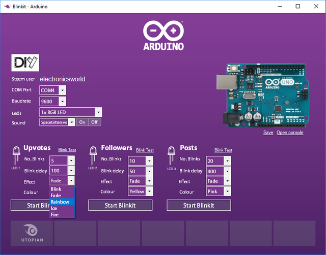
After having set all the settings and confirmed what to use, user will have to press save button in order to save the settings and send them to Arduino in order to have it ready to receive new triggers (notice how the standby mode with its pattern stop when you press save as data are being sent to Arduino)
For full details about how the interface works on the code side and how it has been implemented, please get back to @techtek post.
The following files are added to the repository
Many updates have been planned concerning Arduino integration. In fact our aim is to let Arduino reach a point where it can become fully automated and do not require to be directly attached to a pc running Blinkit software but will run itself the same tasks as Blinkit software by its own thus becoming a portable stand alone device for Steem related notifications.
Technical Support
Technical support is available, if you may encounter a problem, or if you want to know if your device is supported or will be supported in the near future.
How to contribute?
Do you have a question, or suggestion about the integration of Arduino in Blinkit ? Feel free to contact me on Discord (eliaraysalem#0829) or leave a comment below.
مجهود جميل عزيزي كالعادة :)
حصلت على تصويت من
@arabsteem curation trail !
و تم اختيار مقالتك ضمن مقالات يومية مختارة للنشر في مقالنا اليومي
يمكنك الحصول على تصويت اضافي عبر ارسال مبلغ اقله
0.05
ستيم او اسبيدي الى حساب التصويت الالي
@arabpromo
مع رابط المقال في حقل المذكرة (memo)
مما يتيح لك الحصول على تصويت مربح بحوالي 2.5 اضعاف :)
thank you @arabsteem ! much appreciated :D
Nice read. I leave an upvote for this article thumbsup
Join our Discord Channel to connect with us and nominate your own or somebody else's posts in our review channel.
Help us to reward you for making it ! Join our voting trail or delegate steem power to the community account.
Your post is also presented on the community website www.steemmakers.com where you can find other selected content.
If you like our work, please consider upvoting this comment to support the growth of our community. Thank you.
thank you @steemmakers ! much appreciated :D
Thank you for your contribution. Sorry for the confusion, but you should always add the commits you have worked on as well as your repo and not the main repo.
Your contribution has been evaluated according to Utopian policies and guidelines, as well as a predefined set of questions pertaining to the category.
To view those questions and the relevant answers related to your post, click here.
Need help? Write a ticket on https://support.utopian.io/.
Chat with us on Discord.
[utopian-moderator]
thank you for moderating my post ! appreciate the discussion we had on discord and the solution found to everything !! Thanks again !!
Hey @electronicsworld
Thanks for contributing on Utopian.
We’re already looking forward to your next contribution!
Contributing on Utopian
Learn how to contribute on our website or by watching this tutorial on Youtube.
Want to chat? Join us on Discord https://discord.gg/h52nFrV.
Vote for Utopian Witness!
thank you !! much appreciated !!