Project Arduino: Lighting controller in the apartment
For a long time I have been tempted to make myself a reliable light control system in the apartment. Do it, do not buy it ready, because in it all the fun. Long ended on plans, but finally it worked! :)
The assumptions of the project were as follows:
- enabling lighting control at home in the most reliable and simple way possible.
- the dimensions of the controller must be as small as possible, as small as the home production conditions allow.
In view of the above, after verifying my long-term stock of electronic components, I found that I would be fully satisfied with the control using a TV remote control. The remote control usually lies at hand, there are a lot of buttons in it that you do not use, so why not use them to turn on the light?
I used the Arduino to build the prototype in combination with the infrared receiver TSOP 2236 and the integrated Darlington system ULN2003A. The cicrcuit below:
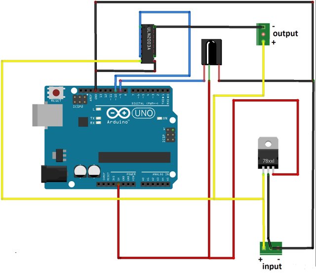
I implemented the program for Arduino in such a way that after turning the power on I have about 2s on pressing a button on the remote control in order to memorize it in my memory. Then Arduino goes into normal operation mode and receiving the programmed code results in switching on the light.
For the input of the above circuit I assume the supply of 12V DC voltage. The same voltage will appear at the output of the circuit when TSOP 2236 receives the correct IR remote code previously memorized by Arduino.
The microcontroller, after receiving the proper IR code of the remote control, which reads on port 9, changes the status of port 10 to high. This in turn triggers the ULN2003A system. Its mass appears on its output. As a result, the desired voltage appears between the voltage given at the input (yellow wire in the diagram) and the output ULN2003A.
A receiver with a rated current of approx. 2A can be connected to the 12VDC output controlled in this way (in my case I control LED lighting bars in this way). If it is necessary to switch on lighting with higher power / higher voltage (eg 230V lamp), it is enough to connect the relay to the output and control the receiver using its contacts.
I marked the 5V voltage line from the stabilizer 7805 with red. This voltage is required for Arduino and the IR receiver. The higher voltage will of course damage the micro-controller, so I do not advise you to try;)
The prototype made on the Arduino board proved to work as it should, but it did not meet my expectations as to the dimensions of the device, which is why I completed the final design of the circuit, the fruit of which is such a plate with dimensions of 44 mm x 26 mm:
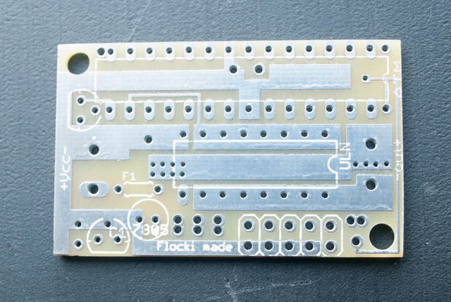
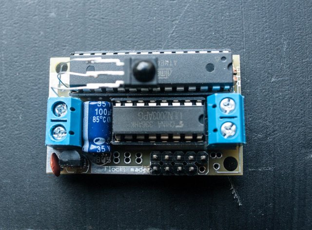
The smaller one could not be performed on the assumption that it will be soldered by a THT method.
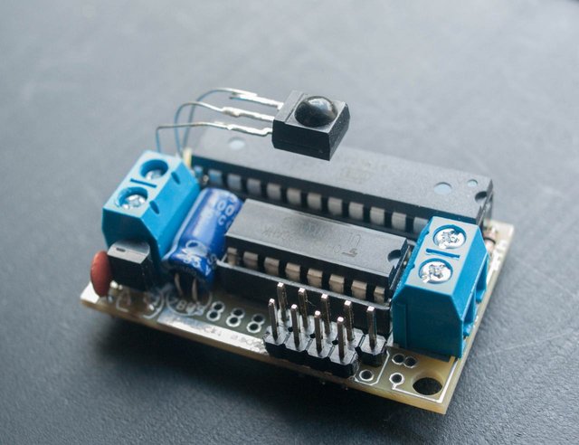
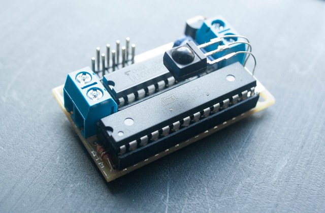
However, these dimensions are small enough for me and I am fully satisfied with the effect. The plate fits easily into the box under the LED lighting switch, under my shelves. For quite a long time I was wondering how to hide the controller with a 230V lamp. Finally, in my workshop, I found a 12V switching power supply, which after opening as it turned out, has enough space inside to put an insulated board in it, along with a miniature relay:
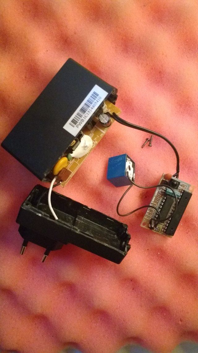
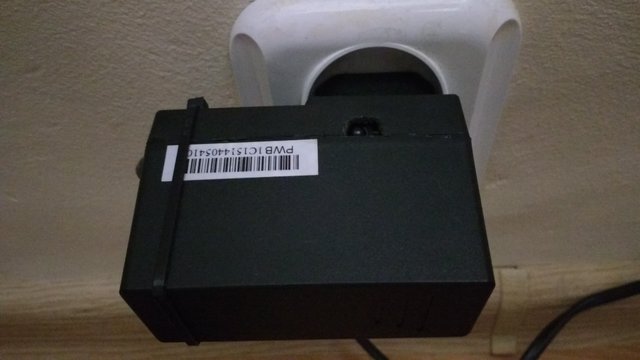
In this case, I gave up the blue, screw ARK connectors for input and output, and sockets for integrated circuits, which further reduced the size of the board. After assembling the casing, the whole looks like a normal power supply, except that the cable goes directly to the lamp, and the housing has a small hole through which the TSOP2236 receives signals from the remote control:
Of course, I've made more board for stock, because doing just one art is not economical with the goal. Besides, I still have some lights at home, which I will want to modify for my driver :).
This is how it looks when you work with LED strips:
And in the case of a 230V lamp:
If someone is interested in the Arduino code, I share it on Github:
https://github.com/flockii/IRRemoteLight
I used the Visual Micro framework for Arduino, but you can copy and use it manually in a normal Arduino IDE.
An IRRemote library is required, available on the Arduino project website.
In this way, without moving from the chair, I can snap all the lights around with a remote control for TV. The sense of the original solution - priceless, fun while building amazing. I recommend it to anyone who likes to play with electronics.
What can you add here?
I am thinking of a central IR transmitter from which I could send signals to all devices from the ceiling, for example. If I go for it, it will be equipped with a cheap WIFI module. This will open up a whole range of possibilities, such as control from the application on the phone or via the website. It will be a whole lot of fun.
Another modification is the implementation of a 2-directional transmitter-receiver IR transmission. I could then send back information about various parameters depending on the needs, for example:
- temperature,
- voltage
- humidity
- dust
Then it will not be just a lighting controller, but the nucleus of the IR-based system such as "intelligent home made building" :). Time will tell if I can accomplish these plans. If so, I will definitely share them here.
The solution is definitely not a breakthrough or "high end", but it provided me with a lot of joy. I had to delve into interesting IR broadcasting solutions, design a PCB, finally write a piece of code and take some time to test and fix. I recommend to anyone who likes electronics and programming, because at the end is a gift in the form of a working, own device and more knowledge. I wish you good luck!
Please resteem if you like this project:)
hello~ good post
Thank you!:)