Microcontroller: Using ESP with Switches and a Web Page to Control Electrical Outlets - Part 2
In this Part 2 of a 2 Part Series - We will be combining the previous switch controlled LED light project (part 1) with the first ESP8266 microcontroller project post that had web page controlled household electrical outlets: Microcontrollers: Using ESP to Control Electrical Outlets from a Web Page.
For Part 1 of this 2 Part series, a standard household Light Switch was added to the ESP8266 microcontroller - using the Arduino IDE programming environment. After programming, uploading, and wiring the circuit for the switch the circuit for the switch, the switch turned on and off the blue LED light that is on-board the ESP8266. Microcontroller: Programming and Wiring a Switch Circuit for ESP - Part 1
This 2nd part of the series will involve copying the switch code created from the Button_ESP Arduino IDE sketch, and adding that code to the Wireless_Relay Arduino IDE sketch that was programmed to control electrical outlets from a web page.
Migrating the Button_ESP Variable Declarations to the Wireless__Relay Sketch
Below are the two programs - or Arduino Sketches - open side by side. On the Left is the Button_ESP sketch we want to merge into the Wireless__Relay sketch on the Right. At the same time we will be making two buttons instead of just one.
- On the Left you can see the variable declarations of the Button_ESP sketch being copied.
- On the Right you can see the button variables being pasted twice into the Wireless__Relay sketch.
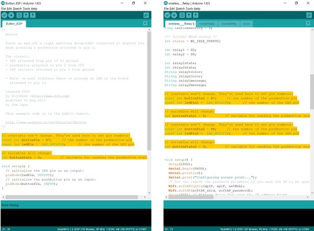
- Notice in the above-right screen capture that the 1 was added to the variable ends of the first button variable declarations of buttonPin, ledPin, and buttonState.
- A 2 was added to the second button declaration variables.
- D7 and D8 were changed to be the buttonPin numbers.
The buttonPin D7 and D8 values are referring to the Digital In/Out pin of the microprocessor. In this case we will be using them as Digital In pins to receive the light switch wired message.
Migrating the Button_ESP Setup { } to the Wireless__Relay Sketch
Below are the two Arduino Sketches open side by side. On the Left is the Button_ESP sketch we want to merge into the Wireless__Relay sketch on the Right.
- On the Left you can see the setup { } contents of the Button_ESP sketch being copied.
- On the Right you can see the setup { } contents being pasted twice into the setup { } section of the Wireless__Relay sketch.
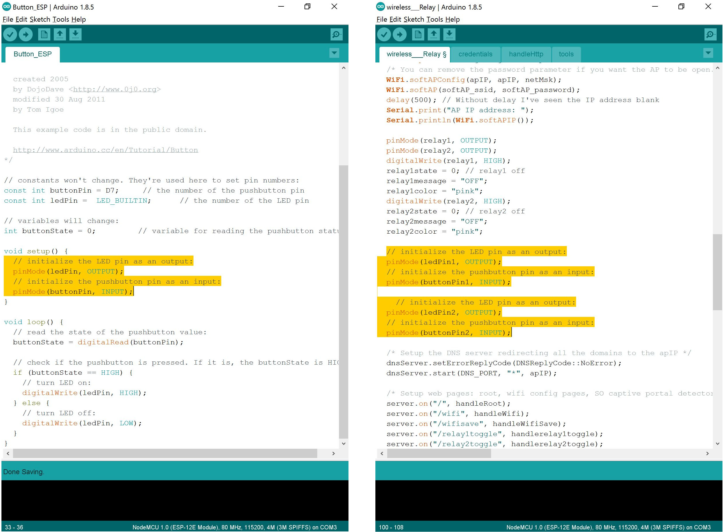
- Notice in the above-right screen capture that the 1 was added to the ledPin and buttonPin variable ends of the first button, and a 2 to the second button.
Migrating the Button_ESP Loop { } to the Wireless__Relay Sketch
Below are the two Arduino Sketches open side by side. On the Left is the Button_ESP sketch we want to merge into the Wireless__Relay sketch on the Right.
- On the Left you can see the loop { } contents of the Button_ESP sketch being copied.
- On the Right you can see the loop { } contents being pasted twice into the loop { } section of the Wireless__Relay sketch.
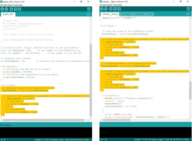
- Notice in the above-right screen capture that the 1 was added to the ledPin and buttonPin variable ends of the first button, and a 2 to the second button variables.
Change Variable Names with Find - Replace All
Now we are going to use the Find and Replace All command to change the variable names so they relate to our new project. Pressing CTRL-f on the keyboard or going to the Edit pull-down menu in the Arduino IDE and selecting Find will open the Find window. As you can see in the screen capture below to the left:
- ledPin1 had been entered into the Find text box.
- relay1 has been entered into the Replace text box.
- Click the Replace All button to replace all the instances of 'ledPin1' in the sketch.
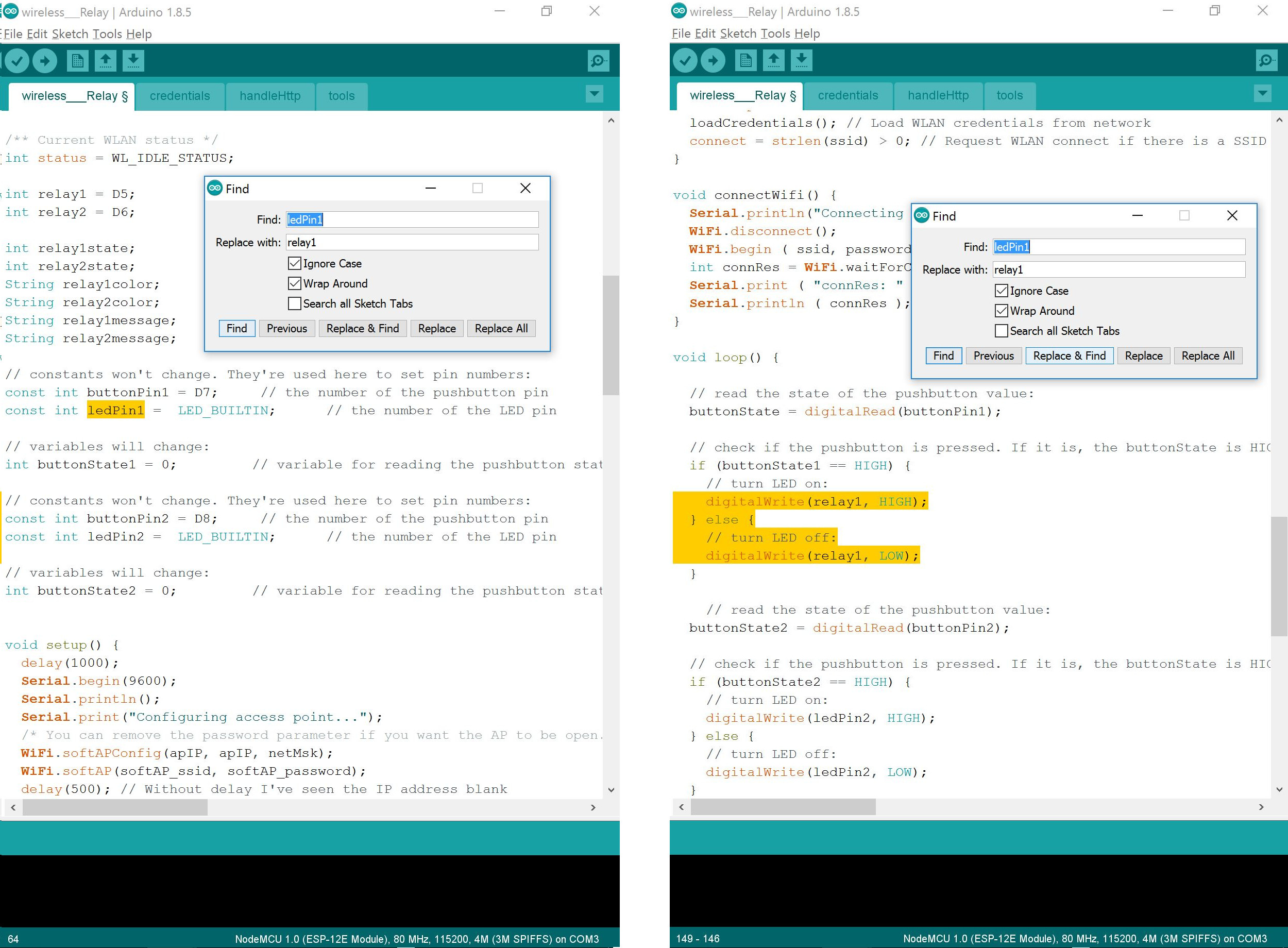
You can see in the picture above on the right that the text has been replaced. For this sketch with relays instead of an on-board LED, it seems more understandable to call them relayPins.
As you can see in the screen capture below to the left:
- ledPin2 had been entered into the Find text box.
- relay2 has been entered into the Replace text box.
- Click the Replace All button to replace all the instances of 'ledPin2' in the sketch with 'relay2'.
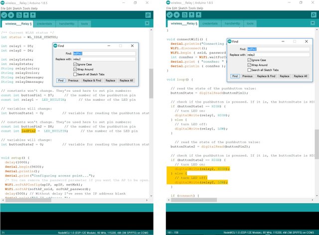
You can see in the picture above on the right that the text has been replaced. For this sketch with relays instead of an on-board LED, it seems more understandable to call them relayPins.
Remove Code that is no longer needed
- In the picture below on the left side you can see the highlighted relay1 declaration that is no longer needed and would cause an error during compiling. If you look up the screen from the highlighted relay1 - you will see that the relay1 was already declared in the Wireless__Relay sketch.
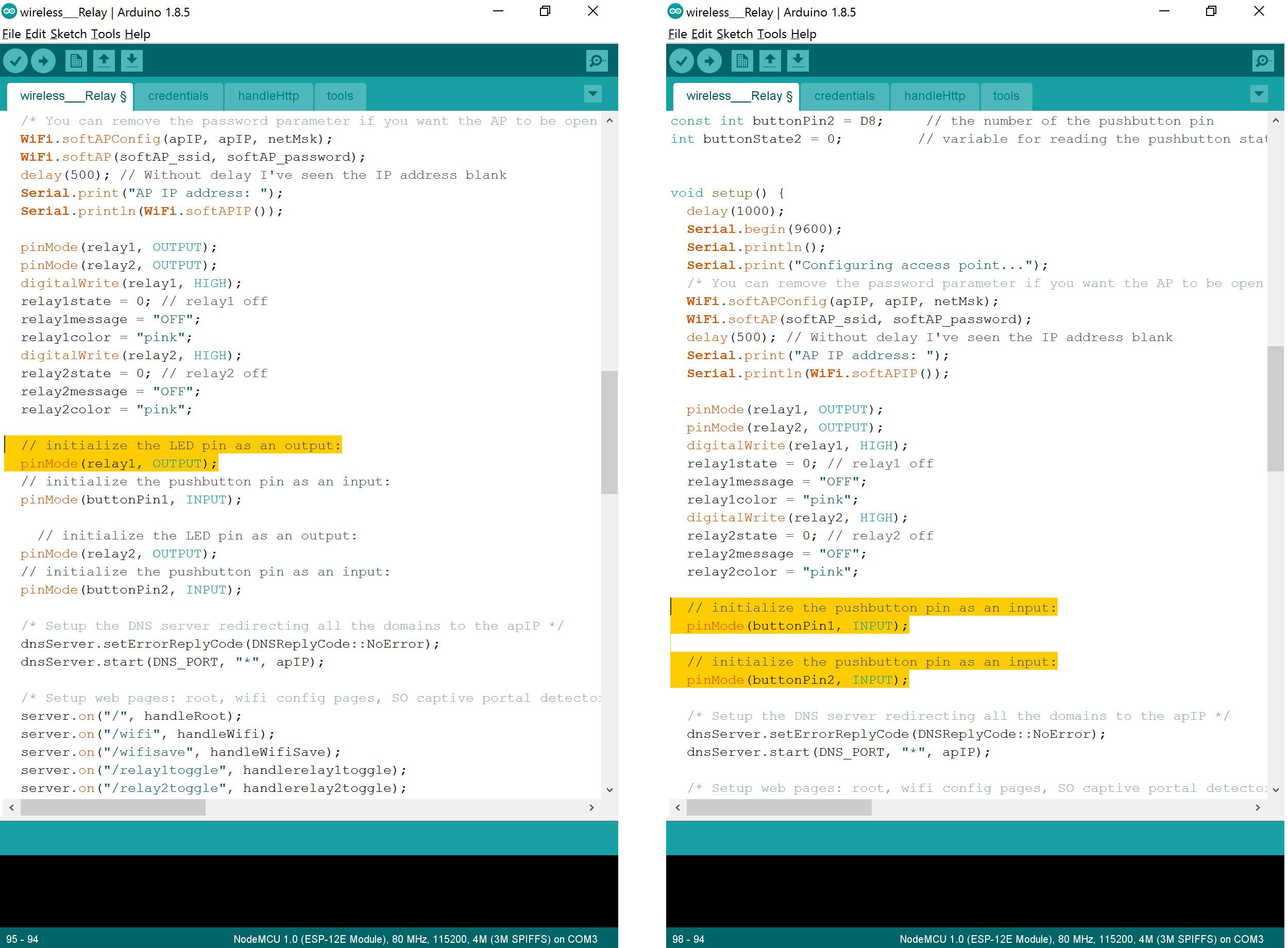
In the screen capture above and to the right you can see the cleaned up code with the removed extra relay1 and relay2 declarations.
Adding the New Code to the Relay Program
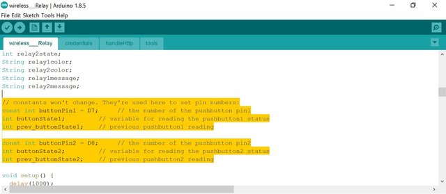
In the screen capture below you can see the 'prev_buttonState1' and the 'prev_buttonState2' integer variables have been added to the variable declaration section at the top of the sketch.
In the screen capture below you can see I added the - delay(250); - line to the top of the loop { } section. The 250 is milliseconds, so this loop will run and check the switches status only 4 times per second. This gives the WiFi handler of the ESP8266 microcontroller more time to handle the WiFi communications.
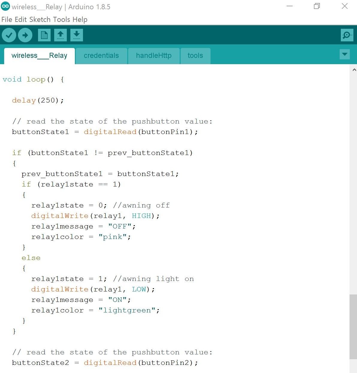
In the screen capture above you can see the alteration of the loop switch code. The changes had to compensate for the web page turning the relay electrical outlets on or off as well. As the loop was running, after turning on or off a relay from the web page, the switch loop would just quickly turn it on or off - depending on the position of the switch. The current position is recorded. When the switch position is checked - if it has changed, then the electrical outlet on-off status is toggled. Turned off if it was on and on if the electrical socket was off.
Arduino Reference: if...else [Control Structure]
- x == y (x is equal to y)
- x != y (x is not equal to y)
- x < y (x is less than y)
- x > y (x is greater than y)
- x <= y (x is less than or equal to y)
- x >= y (x is greater than or equal to y)
The completed Wireless_Relay_Switches sketch is complete and ready to be complied and uploaded.
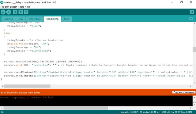
Upload Error from Attached Wiring
As you can see in the screen capture below, I received an Error during upload.
Upload Error Wiring Fix
I realized that I had the switches pin plugged into the microcontroller 3V3 and the relay power pin plugged into the VIN microcontroller pin. Powered micro-devices can sometimes interfere with pins for uploading.
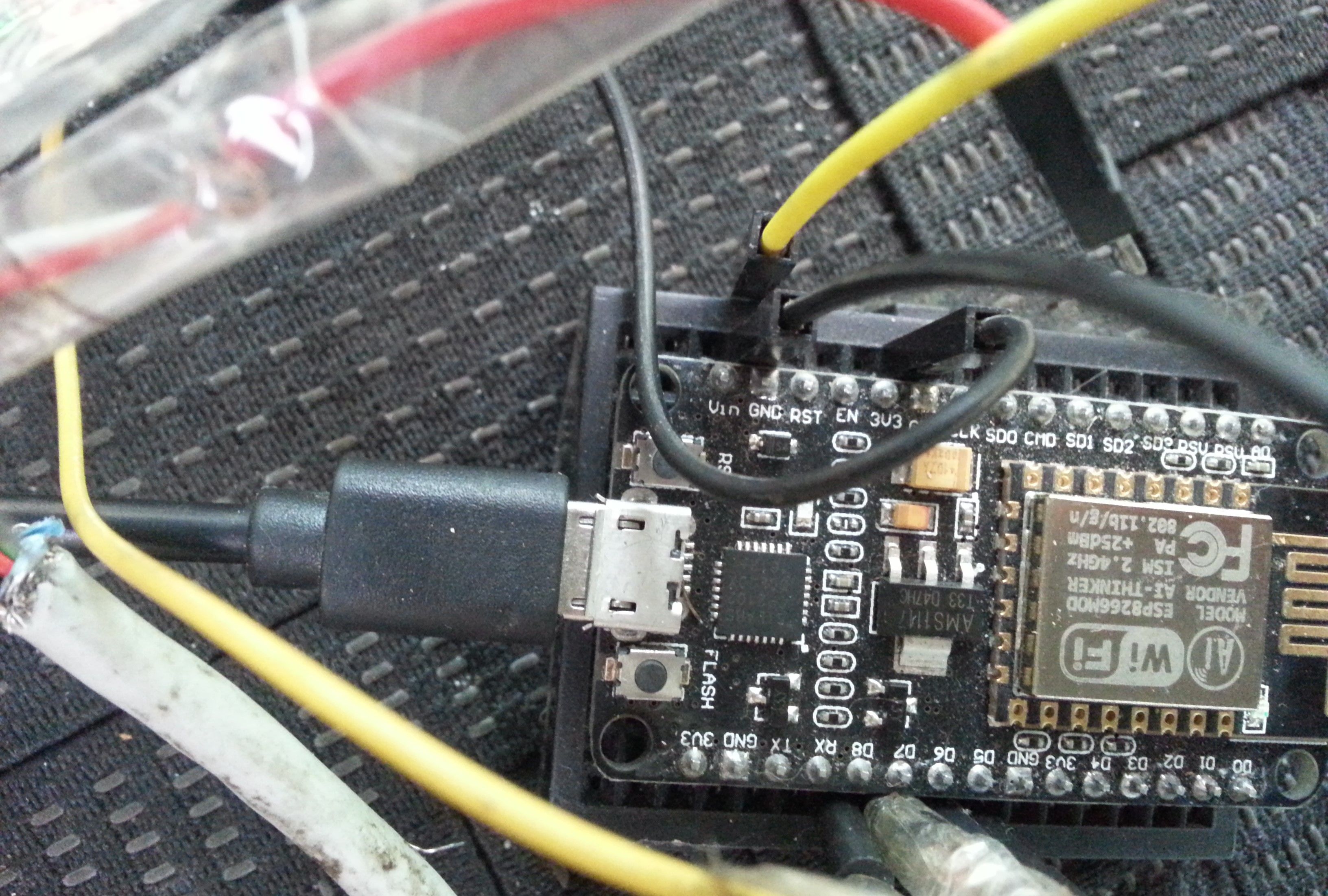
In the picture above you can see I've removed the pins from the 3V3 and VIN on the microcontroller bread board, then precede with the program upload to the ESP microcontroller.
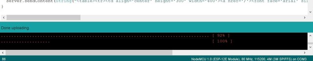
As you can see in the screen capture above, the program Upload finished this time without an upload error.
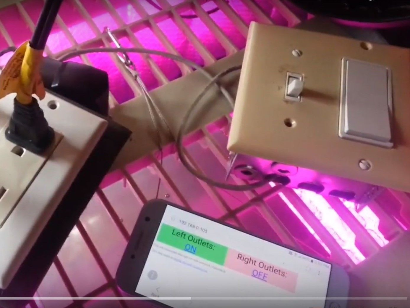
Test of the New Code and Switches Video
Final Combined Projects Assembly
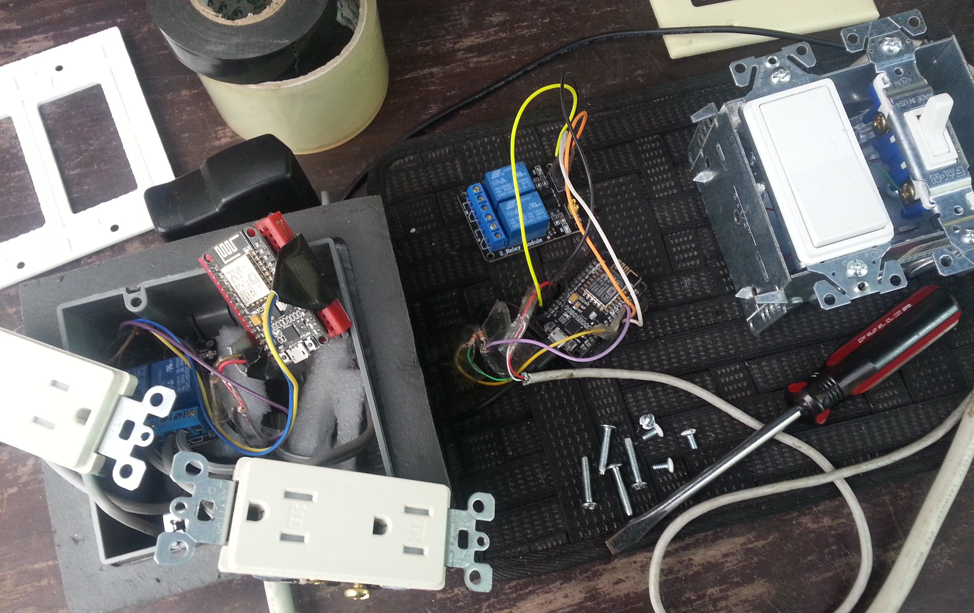
In the picture below you can see the two project hardware that needs to be combined. On the left is the original web page controlled outlets, on the right is the newly completed project with the two switches.
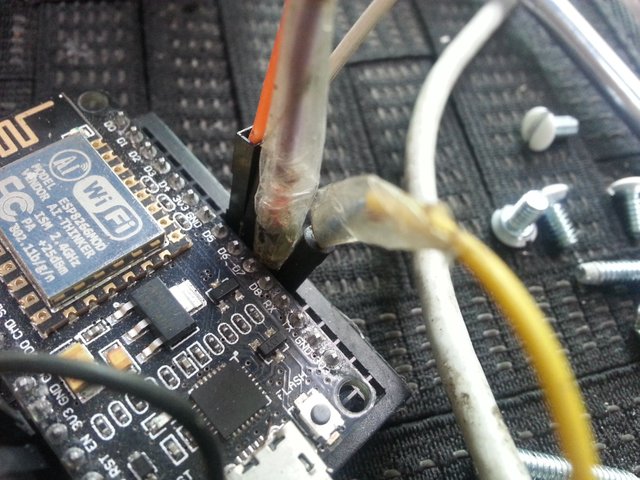
An easy way to remember which color wires go into which microcontroller pins is to take a picture of the board and the pins before disassembly.
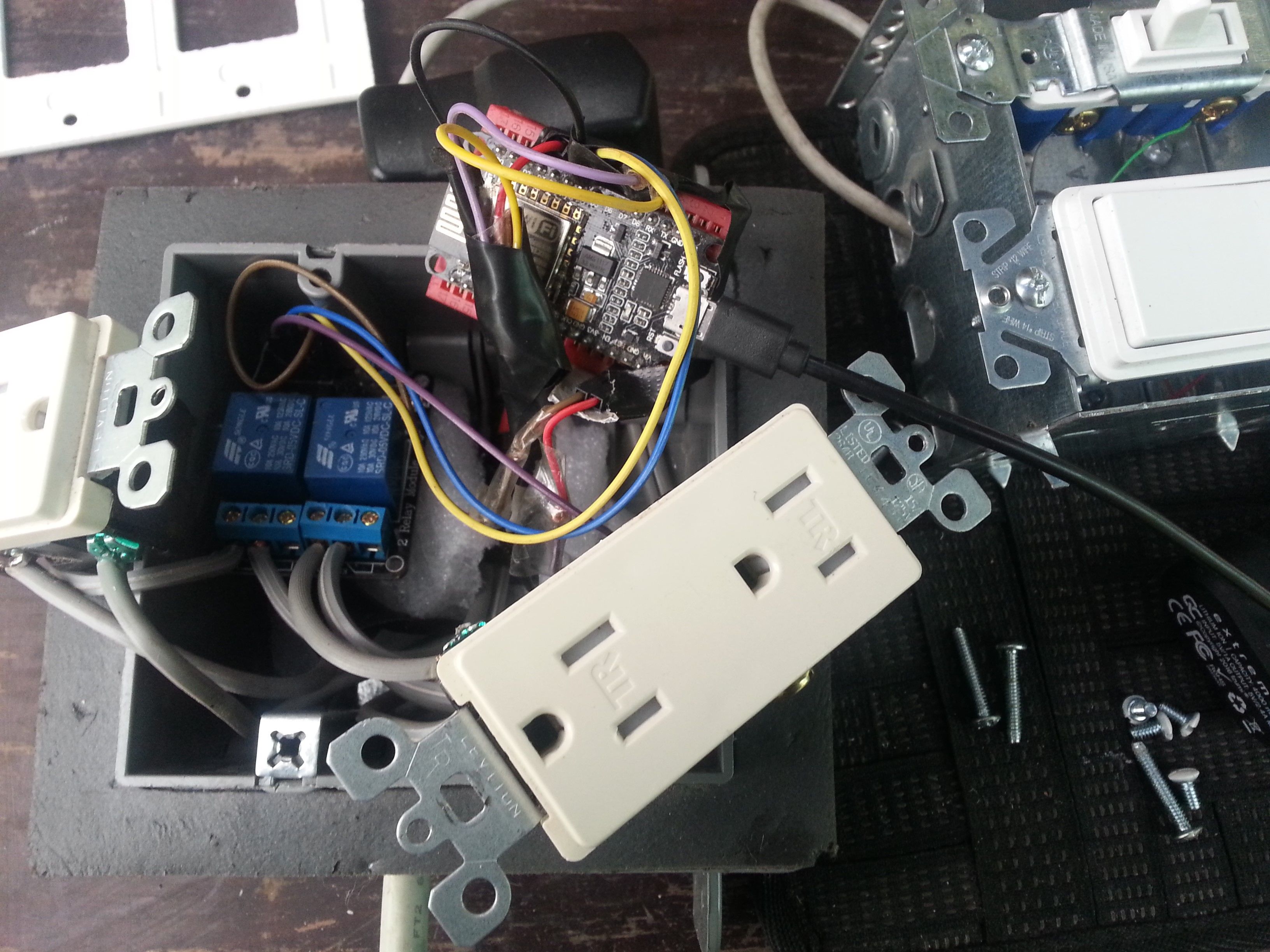
In the picture below you can see the program has been uploaded to the ESP in the electrical outlet box, the wires for the switches have been connected.
Final ESP Web Page and Switch Electrical Outlets Testing Video
Web page controlled Electrical Outlets - with Switches - could be the start of may useful projects. Add a temperature sensor and a plug in heater and air conditioner - a web controlled digital thermostat. Program Internet weather forecasts to change the temperature accordingly to make it more cozy. Adding time to the programming with manual time entry or Internet time lookup would be useful for setting on and off schedules for the controlled electrical outlets. Adding a voltage sensor to this setup could be useful to off-grid systems on backup battery so the controlled electrical outlets would automatically turn off when power was getting low. Now that the microcontroller and Arduino IDE basics are out of the way, the next microcontroller projects will be more complex.
Project Files:
Arduino IDE Button Example
Wireless__Relay Arduino IDE Project Files from the Microcontrollers: Using ESP to Control Electrical Outlets from a Web Page Post: PROJECT ZIP FILE Link:
COMPLETED PROJECT FILES Wireless_Relay_Switches Arduino IDE Sketch: Project ZIP Link:
Have a great day!
Congratulations! this post got an upvote by @steemrepo and was manually picked by the curator @yandot to be added on STEEM REPOSITORY, simply comment "YES" and we upload it on STEEM REPO website.
Wants to know more about the Steem Repo project? Contact us on Discord
Wow! Now that's a process post! This may definitely be a project we try out inside the makerspace I'm opening!
Maker space, nice. I post these microcontroller posts once a week or so now. I'll be exploring various sensors, and controls, eventually some servo projects and some raspberry pi things. Congratulations on opening the maker space :)
Well this post earned you a follow, so I'll definitely be keeping an eye out!