Thinking Inside the Box: MakerCase
Greetings, travelers!
Today's STEM post is a quick tip about a great web app that allows you to creat simple and more complex Box vectors parametrically, that can be digitally fabricated using CNC machinery, like a Router or a Laser.
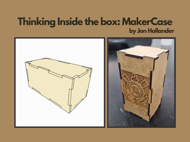
Original image made on Canva using a screenshot from the web app and an original photo of mine of a finished model.
First things first, you can acces the web app at MakerCase.com. The current version of the software was developed in 2019 by Jon Hollander, and if you end up using it, I suggest you buy him a coffe !
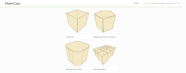
When you enter the website, you can choose from four different types of box creation modules: simple, polygon (with 3 or more sides), with round corners and with dividers. For this example, I'm going to illustrate what is like to create a Simple Box, but I have used all of them successfully.
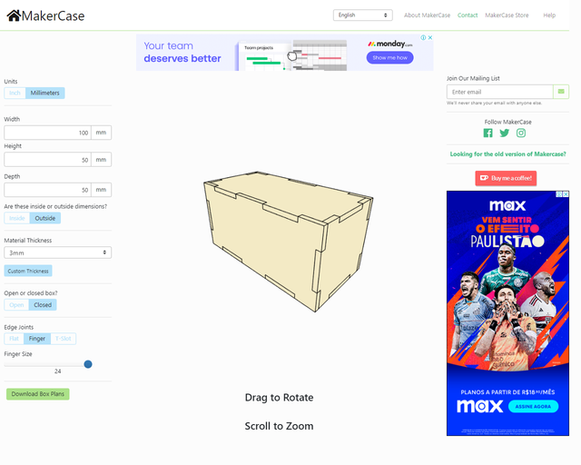
Inside the editor, there are nine different configurations for you to set:
- Units can be set to Inches or Milimeters;
- Width, Height and Depth of your desired box, and make sure to select below them if these are the Inside or Outside dimensions of it;
- Material Thickness has some default options, for example 3mm (1/8 inch) is the one I usually use for smaller boxes and 6mm (1/4 inch) for bigger boxes, but you can also set a Custom Thickness;
- Select if the box is Open or Closed, it is important to notice that having it be Open means there won't a top piece nor edge joints on the upper side of the side pieces;
- Select how the Edge Joints will be designed: Flat makes the joints straight, Finger is the one on the image and T-Slot creates T-shaped slots on the joints that allow for adding additional T pieces for the joinings;
- If you selected Finger Edge Joints, you can set the width of the fingers on the slider bellow the previous options selector.
When you finish setting your configurations, clicking the green button "Download Box Plas" will initiate the vector generating process and allow you to review it before downloading.

There are three separate tabs on the vector settings: Labels and Spacing, Line Formatting and Kerf and Corner Compensation. The first two are straightforward, so I'm just gonna comment about the last one. Kerf allows you to offset the vectors in order to compensate for the width of the tool you're using for machining, which can be a drill bit or the laser itself; since I was gonna use a CNC Laser with approximately 0.2mm of thickness, I selected this option and set the number to 0.1mm, the thickness over 2 (that is explained above the number in the screenshot, but for some reason in Portuguese). Corner Compensation* is a really useful option aswell, that creates a circle in each corner, again with the diameter of your tool. It is used to improve the fit in the Edge Joints, since the tools used in machinery are usually round, a fact that makes it impossible for them to create straight corners. If I can state one criticism, and I'm sure I can, it is that it should be possible to select both the Kerf and Corner Compensation at the same time.
Once your satisfied with the vectors, you can choose between downloading it in SVG format or DXF format, depending on the software you use, and also select if you want it inside a Single File or Multiple ones.
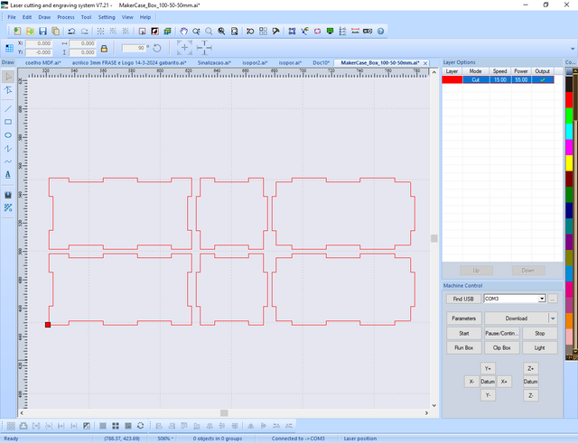
Having your vectors downloaded, you can now open them in your G-CODE generator software for your CNC Machine. The G in G-CODE stands for Geometry, and is the instructions format used in CAD/CAM processes, where you take vectors or 3D models from a CAD software (Computer Aided Design) and create instructions to materialize it using a CAM hardware (Computer Aided Machinery). There are many variants of G-CODE, and it is important to use specific software for your CAM.
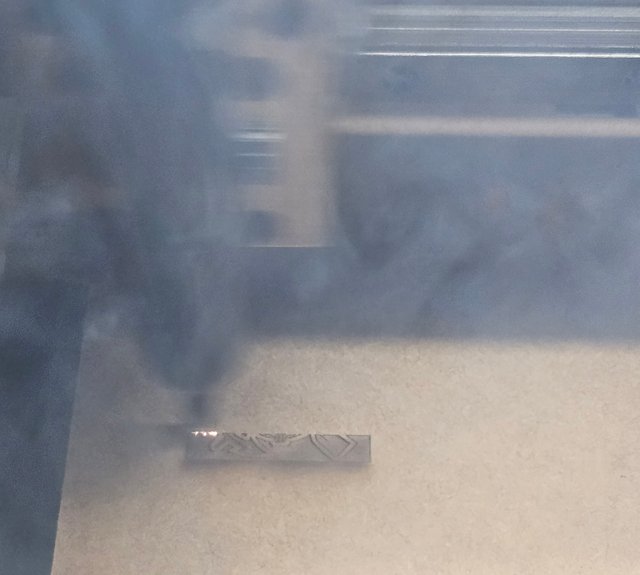
Maybe if there is interest I can create a post where I explain in more depth about CAD/CAM processes and CNC Laser machining, but for now I think the above image illustrates really well the method used. I set an origin point within the machine, and it uses it as reference to then direct the laser tool precisely through the path of the vectors. One nerdy curiosity is that the algorithm used in the softwares that generate the G-CODE are solutions to the Traveling Salesman Problem, since vectors are nothing more than a collection of points, and machining it consists of passing through each point at least once. In the photo, the machine is engraving the emblem of my dear Brazilian footbal club, Corinthians, that I added after taking the previous screenshots because I thought it would complement well the box.
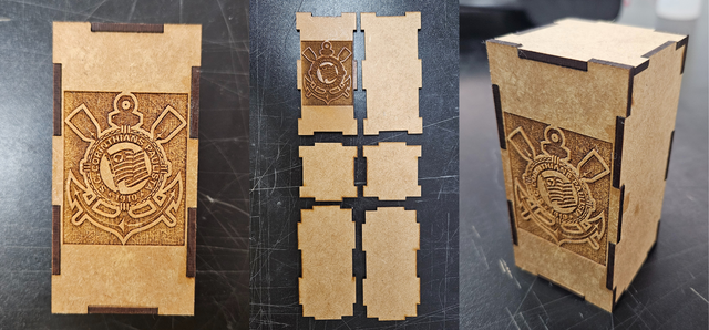
After cutting the pieces of the boxes, I made some post-processing using sandpaper, furniture polish and varnish. I glued all the joints using superglue, and left just the top piece without it, in order to be able to open it.
As stated in the Box type at the homepage of MakerCase, this is definetely a Simple Box, however I'm sure that it is a very powerful tool that can speed up a lot of the workflow when creating vectors, and it has been reliable to me for some years now. It is important to register how important it is to experiment with the configurations, specially the Kerf options, since the precision of the fit between the edge joints depends intrinsically on it.
I hope you found this post interesting! If you do use the tool, please make sure to comment here on your experience. If there are any questions, please do ask them, and I'll do my best to aid. I wish you a great end of the week, and a marvelous weekend! Cheers :)