Let's script: BDP Tower / Scriptiamo insieme BDP TOWER [ENG/ITA]
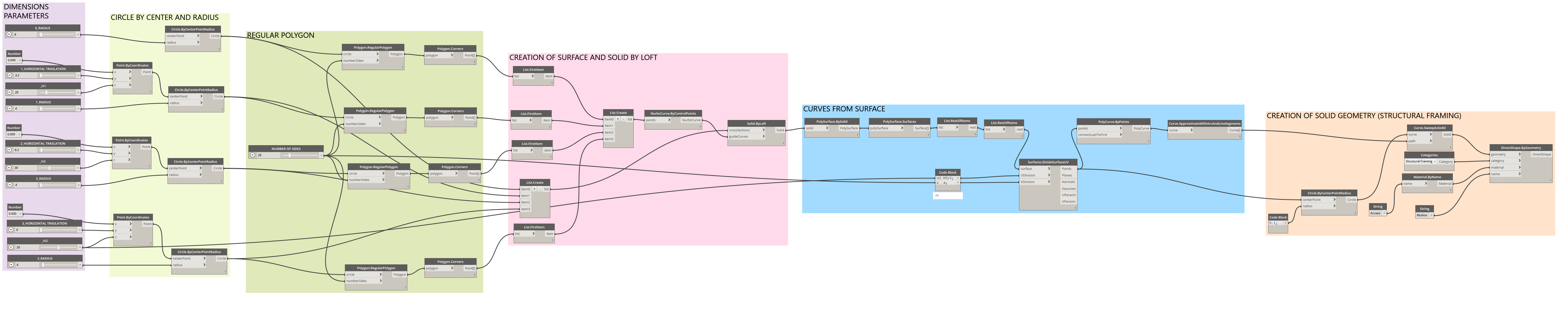
SCRIPT (you can clic to open and zoom on)
Hello to everybody!…
Today, as promised I will present "something practical", to be tested in the first person.
What do you need:
-Dynamo (If you do not know what it is and what you need to find my previous article in my steemit page).
Find the stand-alone version of the Dynamo studio on the official website, or the integrated version within Revit.
If you do not have any programming experience, keep these tips in mind before doing anything:
Set the MANUALscript run immediately, at the bottom left of the main screen.
Sometimes Dynamo crashes on his own, without particular reasons. So it is convenient to save often (on C, better not to use the server).
DO NOT use for while and loop nodes. You could crash the pc
DO NOT script in a model shared with others. In case you have a local file connected to a Revit Control Panel, before testing the script, make a specific central template, detached from that of the others.
NEVER use a script while someone else is using it (because it may be saved on the server). Even here there is a risk of crashes.
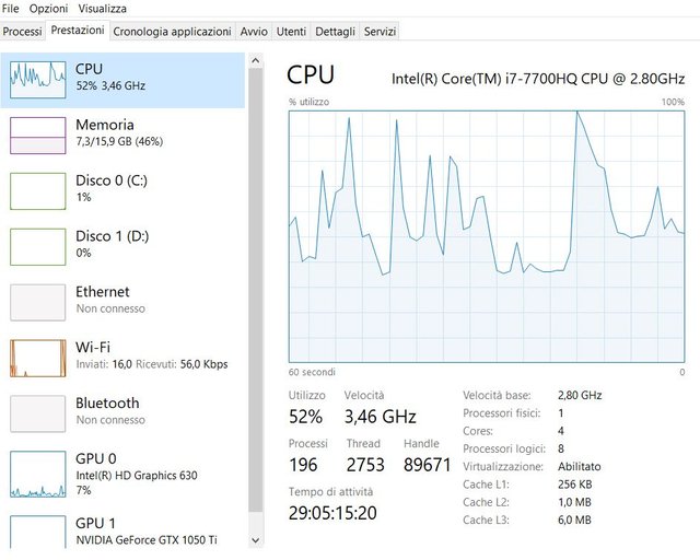
ATTENTION: Check the characteristics of your PC before starting the exercise. The final script takes a few minutes to run, (in about 8 minutes) I advise you if you do not have particularly good computers to keep the number of sides of the inscribed polygons of less than 15.
In any case, here you will find the performance screen while the script is running, then evaluate well according to the machine you have if you want to proceed to run it.
-----ITA------
Ciao a tutti…
Oggi, come promesso vi presenterò “qualcosa di pratico”, da provare in prima persona.
Di cosa avete bisogno:
- Dynamo (Se non sapete cos’è e a cosa serve trovate un mio articolo sulla mia pagina steemit).
Trovate la versione stand-alone Dynamo studio nel sito ufficiale, o la versione integrata all’interno di Revit.
Se non avete nessuna esperienza di programmazione, tenere bene a mente questi consigli prima di fare qualsiasi cosa:
- Impostare subito il run MANUALE dello script, in basso a sinistra nella schermata principale.
- Ogni tanto Dynamo si blocca di suo, senza motivi particolari. Quindi è conveniente salvare spesso (su C, meglio non usare il server).
- NON USARE MAI nodi di for while e loop. Potreste mandare in crash il pc
- NON scriptare MAI in un modello condiviso con altri. In caso aveste un file locale collegato a un Centrale di Revit, prima di testare lo script, fatevi un modello centrale apposito, staccato da quello degli altri.
- NON usare MAI uno script mentre lo sta usando qualcun altro (perché magari è salvato nel server). Anche qua c’è il rischio di crash.
- ATTENZIONE: Prima di procedere all’esercitazione verificate le caratteristiche del vostro PC. Lo script finale impiega qualche minuto perché sia eseguito,(nel mio circa 8 minuti) vi consiglio se non avete pc particolarmente prestanti di tenere il numero di lati dei poligoni inscritti inferiore a 15.
In ogni caso, qua troverete la schermata delle prestazioni mentre lo script è in esecuzione, quindi valutate bene in base alla macchina che avete se procedere praticamente ad eseguirlo.
And now…. Let's start!
We will design the vertical uprights of a completely parametric "free form" tower.
To do this we will follow the following algorithm:
- we will design fully parametric circles in radius and position. In this exercise there will be four: one at the base, two for the central body and the last one that will define the top of our tower. Nothing prevents you from inserting more if you want.
-In these circles we will define regular inscribed polygons, whose number of sides will define how many vertical uprights we will get. - we will create a solid, using the circles as a section and the third-degree curve constructed by joining the angles of the polygons, so as to give an organic form to the tower.
- From this solid free form obtained, we will select the vertical surface, and divide it according to a vertical and horizontal grid. This grid will be parametric, following the formulas initially set.
- We build our mullions, as solid objects (I will give a circular section, but you could draw any other shape) that will follow the parametric grid guidelines, and that will be as many as the number of angles of the inscribed polygons of step 2. A these objects will assign a structural Revit category, and a material.
So we will get our free form façade frame!
----ITA----
Ed ora…. Cominciamo!
Disegneremo i montanti verticali di una torre “free form” completamente parametrica.
Per fare questo seguiremo il seguente algoritmo:
-disegneremo dei cerchi completamente parametrici in raggio e posizione. In questa esercitazione saranno quattro: uno alla base, due per il corpo centrale e l’ultimo che definirà il top della nostra torre. Nulla vieta di inserirne di più se volete.
-In questi cerchi definiremo poligoni inscritti regolari, il cui numero di lati andrà a definire quanti montanti verticali otterremo.
-creeremo un solido, utilizzando i cerchi come sezione e la curva di terzo grado costruita unendo gli angoli dei poligoni, in modo da dare una forma organica alla torre.
-Da questo solido free form ottenuto, selezioneremo la superficie verticale, e la divideremo secondo una griglia verticale e orizzontale. Questa griglia sarà parametrica, seguendo le formule impostate inizialmente.
-Costruiremo i nostri montanti, come oggetti solidi (io darò una sezione circolare, ma voi potreste disegnare qualsiasi altra forma) che seguiranno le linee guida della griglia parametrica, e che saranno tanti quanto il numero di angoli dei poligoni inscritti del punto 2. A questi oggetti assegneremo una categoria Revit strutturale, e un materiale.
Otterremo così il nostro telaio di facciata free form!
Practical steps
Open Dynamo (for those who have it integrated in Revit you find it at the top in the Manage toolbar in the upper left)
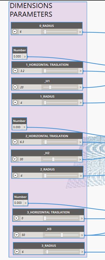
The link between dynamo and revi is automatic, as soon as you start the script it will draw the geometry you have already programmed in Revit.We set the dimensional parameters. The node name is "Number slider", you just have to write it in the Dynamo library search and press enter, and the node will appear in the middle of your screen. By right clicking on the name you can rename it, so you can remember what value you can then modify.
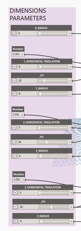
You will need 10 nodes "number slider" and 3 "number", which you can organize in this way:
These will be the parameters that will manage the dimensions of your tower: the rays, the widths, and the more or less curved position
----ITA----
In pratica
Aprite Dynamo (per chi lo ha integrato in Revit lo trovate in alto nella toolbar Gestisci in alto a sinistra)
Il collegamento tra dynamo e revi è automatico, appena avvierete lo script esso disegnerà la geometria che avete programmato già in Revit.Impostiamo i parametri dimensionali. Il nome del nodo è “Number slider”, vi sarà sufficiente scriverlo nel cerca della libreria Dynamo e premere invio, e il nodo comparirà al centro della vostra schermata. Con click del tasto destro sul nome potete rinominarlo, in modo da ricordare quale valore potrete poi modificare.
Avrete bisogno di 10 nodi “number slider” e 3 “number”, che potrete organizzare in questo modo:
Questi saranno i parametri che gestiranno le dimensioni della vostra torre: i raggi, le larghezze, e la posizione più o meno curva
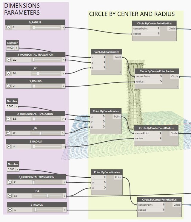
- We create our circles, defining the coordinates of the points and the radius, using the parameters created previously. You will get this:
----ITA----
- Creiamo i nostri cerchi, definendo le coordinate dei punti e il raggio, utilizzando i parametri creati in precedenza. Otterrete questo
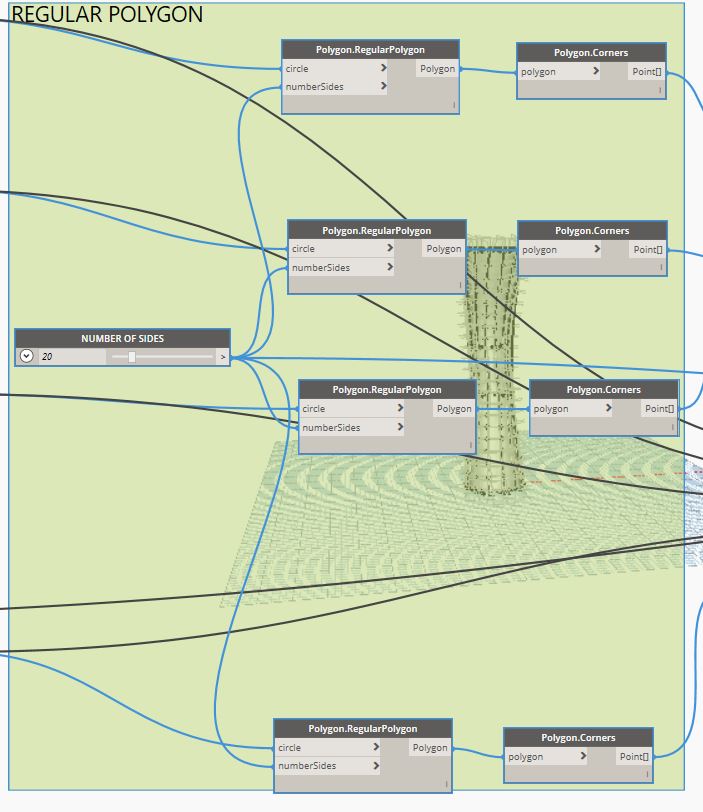
- We inscribe in regular polygon circles, parameterizing the number of sides:
----ITA----
4)Inscriviamo nei cerchi poligoni regolari parametrizzando il numero dei lati:
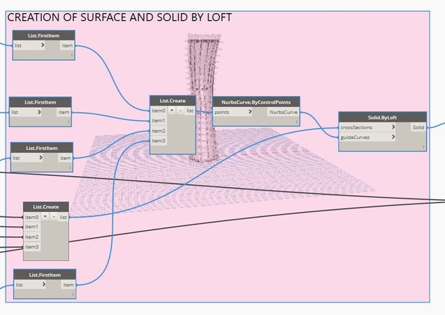
- We select from the polygons all the angles, we take only the first of the list and define a third-degree curve-guide, to be taken as a reference for our tower.
We create a list with all the circles of point 1, which will be the reference sections of the tower.
The "solid by loft" knot will join our circles along the guide curve, creating an organic solid geometry.
----ITA----
5)Selezioniamo dai poligoni tutti gli angoli, prendiamo solo il primo della lista e definiamo una curva-guida di terzo grado, da prendere come riferimento per la nostra torre.
Creiamo una lista con tutti i cerchi del punto 1, che saranno le sezioni di riferimento della torre.
Il nodo “solid by loft” unirà i nostri cerchi lungo la curva guida, creando una geometria solida organica.
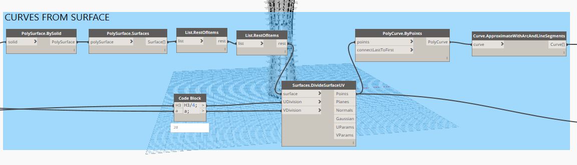
- Now we will have to extract the vertical surface, and divide it according to a UV grid. The parameter U will be defined by the height of the circle at the top of our tower / 4, because I hypothesized 4 meters as an appropriate gross height between one floor and another. The parameter V, on the other hand, is governed by the number of sides defined in point 4. From the points obtained, the curve can be obtained on the surface, through the polycurve by points node. I suggest then to approximate it to segments to make it easier to execute the script.
----ITA----
- Ora dovremo estrarre la superficie verticale, e dividerla secondo una griglia UV. Il parametro U sarà definito dall’altezza del cerchio al top della nostra torre / 4, perché ho ipotizzato 4 metri come un’altezza lorda adeguata tra un piano e l’altro. Il parametro V invece, è governato dal numero di lati definito al punto 4. Dai punti ottenuti si potrà ottenere la curva sulla superficie, attraverso il nodo polycurve by points. Consiglio poi di approssimarla a segmenti per rendere più semplice l’esecuzione dello script.
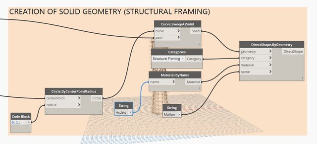
- The final step will be to create the geometry of the uprights with characteristics of the BIM objects, ie category and material.
----ITA----
Il passo finale sarà quello di creare la geometria dei montanti con caratteristiche degli oggetti BIM, ossia categoria e materiale.
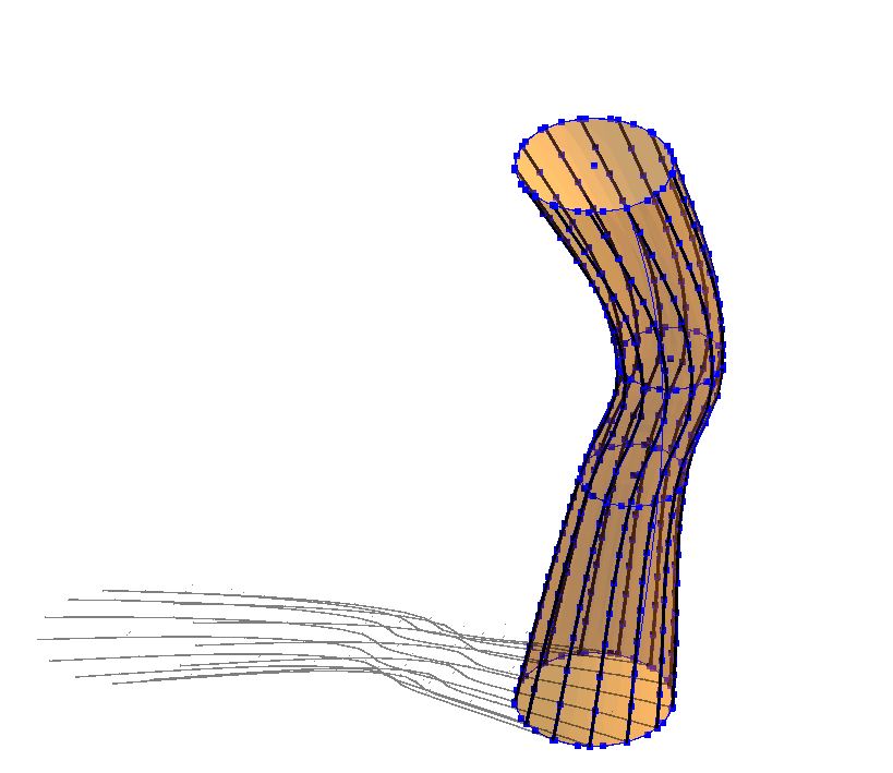
Run by pressing RUN ... and you will have your parametric tower, of which you can change shape and size to study your very own design!
Your design will be like this if you set the same parameters I've setted:
---ITA---
Eseguire premendo RUN… e avrete la vostra torre parametrica, di cui potrete cambiare forma e dimensioni per studiare il vostro personalissimo design!
Il vostro design sarà come questo se imposterete gli stessi miei parametri:
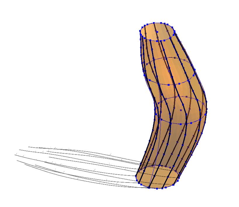
But if you change a little bit the initial values you coud obtain something totally different, like this:
---ITA---
Ma se cambierete un pò i valori iniziali potreste ottenere qualcosa di completamente diverso, come questo:
I hope you will enjoy this exercise,
See you soon!!
---ITA---
Spero vi sia piaciuto questo esercizio pratico,
a presto!
Tutte le immagini sono di proprietà dell'autore/ All images are property of the author
Interesting to play with the parameter, forming organic shapes. That's what I intended to pick up too.
In effetti BIM è veramente di grande fascino. Bel lavoro.
Un saluto, nicola
Grazie, è sempre bello vedere che il lavoro che faccio viene apprezzato!
A presto! :)
Fantastico tutorial! Complimenti davvero molto curato, spero di provarlo presto :)
Grazie! Sono felice che ti sia piaciuto!
PS: Un consiglio... provalo step by step e su un pc con almeno 16 GB di RAM... nel mio ne ha usati 7 abbondanti!
Avevo sentito parlare del BIM nell'ambito di software per la gestione di dati: esempi come cataloghi per ferreamente o per il settore dell'idrotermica. Sono fuori da tempo dal campo dell'informatica e Non avevo capito cosa fosse. Ho letto un po' dei tuoi post, sono sicuramente tecnici ma ho qualche elemento in più 👍Grazie
Grazie del commento!
Hai centrato il tema, il BIM serve esattamente alla gestione dei dati, soprattutto nel settore del real estate.
Un progetto architettonico fornito in BIM ha più qualità intrinseca e molto meno margine di errori di cantiere... Su come poi i dati verranno gestiti e mantenuti nel tempo (anni) ancora è un campo pioneristico!
A presto!
Grazie a te
Ne avevo sentito parlare molto (tra l'altro me l'avevano indicato come il futuro, per quanto riguarda le specifiche su dato - come un oggetto composto da molteplicità di vettori [l'esempio non so se calza] - era alcuni anni fa). ma l'avevo contestualizzato all'argomento e non avevo pensato al fatto che potesse avere un'applicazione anche nel campo della progettazione - anche se capisco che alla fine è senz'altro correlata.
Congratulations @bimdesign.pro! You received a personal award!
Click here to view your Board
Congratulations @bimdesign.pro! You received a personal award!
You can view your badges on your Steem Board and compare to others on the Steem Ranking
Vote for @Steemitboard as a witness to get one more award and increased upvotes!