The Future of Television: Blue Phase LCD
Since the invention of liquid crystal display (LCD) televisions, their sales have increased exponentially, making the traditional cathode ray tube (CRT) televisions practically obsolete due to LCD’s lower radiation risks, smaller power consumption and slim, lighter frames [1]. The application of liquid crystals to television sets has revolutionised the entertainment industry as they feature in mobile phones, televisions, computer monitors and a range of other applications. LCDs do not produce light themselves, except they use a backlight to create images using a large number of pixels [2]. Although LCDs have proven themselves, overtaking CRT displays, they are now struggling to cope with ever-growing technological advances and provide a somewhat disappointing experience for commercial 3D televisions due to slow switching speeds [3]. Blue phase LCDs could offer a solution to this obstacle due to much faster response times, as demonstrated by Samsung in 2008 when they showcased their first blue phase LCD [4, 5]

Twisted Nematic LCDs
The 1970s brought the discovery of the twisted nematic field effect which could be utilised in the advancement of LCDs [6]. ]. Twisted nematic LCDs are best described by the schematic shown in figure 1.
A twisted nematic LCD is made up of nematic liquid crystal layer sandwiched between two glass substrates, which force the directors to align into a helical shape, twisting the liquid crystal by 90˚ as shown in figure 1a. A layer of transparent indium-tin oxide is applied to the glass to act as a conducting layer once voltage is applied, forming a parallel plate capacitor. Once a field is applied, the liquid crystal will align with the field as shown in figure 1b [8]. This layer is followed by polarizers whose axes are perpendicular to each other [9].
This device allows the production of images by use of a back light that passes light (as shown by the white arrow in figure 1) through the first polarizer to create only horizontally polarized light. As this light passes through the glass substrate layer and reaches the liquid crystal it will follow the direction of the liquid crystal molecules. Therefore, if the electric field applied is zero, the light that emerges will be at 90˚ to the horizontal input light, so vertically polarized light will emerge. This vertical light will pass through the vertical polarizer on to a set of colour filters, or pixels. On the other hand, when an electric field is applied to the electrode, depending on the magnitude of the current, the specific alignment of the liquid crystal molecules can be controlled meaning the orientation of light reaching the vertical polarizer can also be controlled. Once this specific orientation of light reaches the vertical polarizer, only vertical light passes through whose intensity will determine the colour output of the pixels by controlling the amount of light and dark [9]. Thousands upon thousands of these pixels make up a LCD, with a different current passing through each liquid crystal, the colour across each element of the screen can be controlled to produce an image.
This technology has proved indispensable in the production of Televisions, Mobile Phones, Watches and Computer Monitors over the past 50 years and will most likely continue to dominate in the production of screen technology in the foreseeable future. However, with recent technological advances came the invention of “Virtual Reality” and public demand requires a more immersive experience in the form of 3D television.
3D TV
There are various examples of 3D screens that use LCDs including parallax barrier displays, lenticular displays and head mounted displays each with their own advantages and disadvantages [10, 11, 3]. One particularly promising liquid crystal application to 3D displays is time sequential displays as their disadvantages have the potential to be overcome with blue phase LCD technology.
Time sequential LCDs use a backlight behind the screen that can change direction. This technology splits the image into two time frames. In each different time frame the back light and image is aimed at the left and right eyes. This results in an ‘eye box’ where a viewer will receive a 3D image due to the overlapping of the images [12].
However, this method comes with complications; namely, the response time, or switch speed. Response time of a Liquid Crystal describes the time between a current being applied or removed to the liquid crystal and the subsequent production of light or dark on the display i.e. how long it takes a pixel to change it’s colour or intensity. Switching off time is usually longer as the liquid crystal needs to relax back into its helical shape [2]. This causes a problem for time sequential LCDs as the liquid crystal shutter cannot be opened until the response time is completed. Meaning, for long response times the image wouldn’t stabilize in time for the next image to be displayed, causing a low-quality image to be produced. Time sequential displays rely on a fast switch speed in order to produce two images quickly enough to avoid a flicker [13, 14]. Blue Phase displays have the potential to offer a solution to this issue.
What is Blue Phase Technology?
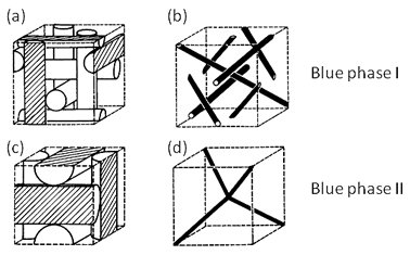
“Blue phase” describes a liquid crystal phase between the helical and isotropic phase of a chiral liquid crystal within a narrow range of temperatures, usually ~1˚C. There are three phases of a blue phase liquid crystal: BPI (body centred cubic lattice), BPII (simple cubic lattice) and BPIII (isotropic structure) [15, 16]. Blue phases are unique from traditional liquid crystal phases as they demonstrate optical isotropy when placed between crossed polarizers regardless of current applied due to their cholesteric arrangement. In addition, they possess a much faster response time, in the sub millisecond range [17, 18].
Structure of Blue Phase Liquid Crystals
In a cubic blue phase liquid crystal, molecules possess a double (unlimited) twist structure contained in a cylinder whose directors can rotate by up to 45˚ from the central line within the limit of the diameter of the cylinder of approximately 100nm. These features give blue phase liquid crystals a “small range local reorientation” resulting in their* fast response time*, with 39 µs being observed [18, 19].
Double twist structure is inherently more stable than a single twist structure, however double twisted cylinders do not fit in a cubic space in such a way that all directors are matched [19]. Defect theory provides an answer to this predicament in that it suggests that defects occur at the crossings of the double twist and cubic structures [20]. Also known as disclination lines, these defects allow the cubic structure to be adopted by the helical molecules [19]. The structure of blue phase liquid crystals is unique as they hold a cubic structure despite being fluids.
The Kerr Effect
The Kerr Effect is used as an explanation as why the optically isotropic blue phase exhibits change under an electric field. The Kerr Effect is a quadratic electro optical effect which can describe why the liquid crystal director realigns once an electric field is applied. Application of an electric field makes the liquid crystal birefringent, thus changing the refractive index according to the polarization direction of incoming light
The Kerr effect causes the blue phase liquid crystal to act as a waveplate and allows light to pass through crossed polarizers. In addition, this effect allows for a quick response time as a small amount of electric field can induce a large change in birefringence provided the liquid crystal has a large Kerr constant [16]. This means that blue phase display’s pixels can change their colour much more rapidly than twisted nematic displays, making them suitable for the double image requirements of time sequential 3D displays. The birefringence of the liquid crystal means that it consists of more than one refractive index which it can switch between depending on the voltage applied.
How can this be used in 3D TVs?
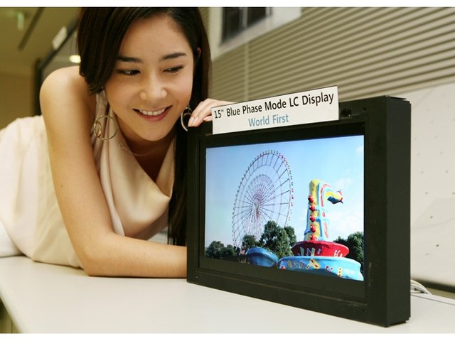
In May 2008, Samsung unveiled the World’s first 15” blue phase LCD. Not only did this screen exhibit unprecedented refresh rates of 240 Hz compared to the standard 120Hz, it also provided a cheaper design due to blue phase’s ability to self-align into cubic structures, eliminating the need for liquid crystal alignment layers and reducing the production cost massively. This technology has massive potential for being able to provide high speed video making it suitable for the rapid response times required for 3D displays. Samsung made a statement proclaiming that they hoped to sell blue phase LCDs commercially by 2011 [21]. However, 7 years on and there is still no evidence of any advances in this technology. This is because, despite blue phases obvious advantages, there are various obstacles that are yet to be overcome [22].
Disadvantages of Blue Phase
One of the major disadvantages of blue phase is the extremely narrow temperature range in which the phase occurs at. Maintaining this small temperature window whilst applying various electric fields to control colour output is extremely difficult [16]. As a result, multiple attempts have been made to increase this window, in order to make blue phase more suitable for display production, including the use of Nano particles and polymer stabilization [23, 24]. A group from Kyushu University made use of polymer stabilizer effects to increase the temperature range of blue phase from ~1°C to ~60°C within room temperature range [25]. This is achieved by creating a composite of polymer/ blue phase liquid crystals by photopolymerization causing a cross-linking polymer network at the disclination lines to increase the temperature range that the phase can hold it’s cubic shape [16].
Another obstacle in producing blue phase displays come from their high operating voltage of numerous 10s of volts as it hinders the abilities of the transistors which are essential for LCDs operation [16]. A high operating voltage is the cause of the ‘electrostriction effect’ which induces unwanted lattice deformities and hysteresis [26].
Operating voltage is determined by induced birefringence which is dependent on The Kerr Constant and electric field applied. In order to obtain a smaller Operating Voltage, the material must possess a large Kerr Constant. Therefore, a method to produce blue phase LCDs with a large Kerr Constant is essential in the production of blue phase displays. One way in which this has been achieved is by increasing the dielectric anisotropy of a material. Increasing dielectric anisotropy is successful in terms of increasing The Kerr Constant to decrease operating voltage. However, a large dielectric anisotropy increases the number of polar groups of the liquid crystal thus increasing the response time [26]. Clearly this would impact negatively on the image production of the LCD.
Conclusion
Blue Phase LCDs offer range of advantages over twisted nematic displays including: a rapid response time, cheaper production costs and faster refresh rates, making them incredibly suited for future production of 3D displays. Despite these advantages, the production process of blue phase LCDs must be refined in order to reduce operating voltage and increase the temperature range of the crystal simultaneously. Once this has been achieved true 3D displays with a quick enough response rate could be produced using blue phase liquid crystals.
Please note that images used in this article have been labelled as re-usable on Google images. If any artists or designers have any issues with the content used, don't hesitate to contact me to correct the issue.
References
- Chiu. Yu-Ting, et al., “Marketing strategy based on customer behaviour for the LCD-TV”, International Journal of Management and Decision Making, Vol. 7, No. 2/3, 2006
- Elze. T, Tanner. T, “Temporal Properties of LCDs: Implications for Vision Science Experiments Tobias”, Public Library of Science. Vol. 7, No. 9, 2012
- Hill. L, et al., “3-D LCDs and Their Applications”, Institute of Electrical and Electronics Engineers, Vol. 94, No. 3, pp. 575-590, 2006
- H. Kikuchi, et al., “Fast Electro-Optical Switching in Polymer-Stabilized Liquid Crystalline Blue Phases for Display Application”, Society for information display, Vol. 38, No. 1, pp. 1737-1740, 2007
- Phy Org, “Samsung Develops World’s First 'Blue Phase' Technology to Achieve 240 Hz Driving Speed for High-Speed Video”, 2008. [Online]. Available: https://phys.org/news/2008-05-samsung-worlds-blue-phase-technology.html. [Accessed 05.11.2018]
- Helfrich. W, Schadt. M, “Voltage Dependent Optical Activity of a Twisted Nematic Liquid Crystal”, Applied Physics Letters, Vol. 18, No. 4, pp. 127-128, 1971
- Nehring. J, Scheffer. T, “Super twisted nematic LCDs”, Annual Review of Materials Science, Vol. 27, pp 555-583, 1997
- Jones. C, “LCDs”, Handbook of Optoelectronics, CRC Press, 2017
- Dunmur. D, Walton. H, “Liquid Crystal Display”, 2015, Encyclopaedia Britannica. [Online]. Available from: https://www.britannica.com/technology/liquid-crystal-display. [Accessed 06.11.18]
- G. Woodgate, et al., “Flat panel autostereoscopic displays—characterization and enhancement”, Proceedings of the SPIE, Vol. 3957, pp. 153–164, 2000
- H. Morishima, et al., “Rear cross lenticular 3-D display without eyeglasses,” Proceedings of the SPIE, Vol. 3295, pp. 193–202, 1998
- Dodgson. N, et al., “A 50" time-multiplexed autostereoscopic display”, Proceedings of the SPIE, Vol. 3957, 2000
- Sehic. A, Woods. A, “The compatibility of LCD TVs with time-sequential stereoscopic 3D visualization”, Proceedings of the SPIE, Vol. 7237, pp. 19-21, 2009
- Boher. P, et al., “Characterization of one time‐sequential stereoscopic 3d display ‐ Part I: Temporal analysis”, Journal of Information Display, Vol. 11, No. 2, pp. 57-62, 2010
- Kitzerow. H, Bahr. C, “Chirality In Liquid Crystals”, Springer Verlag, 2001.
- Balamurugan. S, et al., “Blue phase liquid crystal: strategies for phase stabilization and device development”, Science and Technology of Advanced Materials, Vol. 16, pp. 21, 2015
- Saupe. A, “On molecular structure and physical properties of thermotropic liquid crystals”, Molecular Crystals, Vol. 7, pp. 59–74, 1969
- Rao. L, Wu. S, “Low-voltage blue phase LCDs”, Liquid Crystals Today, Vol. 24, No. 1, 2015
- Chen. Y, et al., “A microsecond-response polymer-stabilized blue phase liquid crystal”, Applied Physics Letters. Vol. 99, 2011
- Meiboom. S, et al., “Theory of the blue phase of cholesteric liquid-crystals”, Physical Review Letters, Vol. 46, pp. 1216-1219, 1981
- Gizmodo, “Samsung Develops New ‘Blue Phase’ LCD Panel for TVs”, 2008. [Online]. Available from: https://gizmodo.com/390255/samsung-develops-new-blue-phase-lcd-panel-for-tvs, [Accessed: 10.11.18]
- Hyeokiin. L, et al., “The World’s First Blue Phase Liquids Crystal Display”, Society for information display, Vol. 42, No. 1, 2012
- Karatairi. E, et al., “Nanoparticle-induced widening of the temperature range of liquid-crystalline blue phases”, Physical Review Journals, Vol. 81, 2010
- Dierking I, et al., “Stabilising liquid crystalline blue phases”, Soft Matter, Vol. 8, pp. 4355–4362, 2012
- Kikuchi. H, et al., “Polymer-stabalized liquid crystal blue phases”, Nature Materials, Vol. 1, pp. 64-68, 2002
- Chen. Y, et al., “A low voltage and submillisecond-response polymer-stabalized blue phase liquid crystal”, Applied Physics Letters, Vol. 102, 2013
- Rao. L, “Low voltage blue phase LCDs”, University of Central Florida, 2012
Congratulations @loular! You received a personal award!
Click here to view your Board
Do not miss the last post from @steemitboard:
Congratulations @loular! You received a personal award!
You can view your badges on your Steem Board and compare to others on the Steem Ranking
Vote for @Steemitboard as a witness to get one more award and increased upvotes!