Repair Course for PCs Old Platforms (486 and up) Part 2 [SpanishTranslation]
1.2.- The Motherboard.
General description.
It is the largest computer board. Supports microprocessor, RAM, cache, expansion slots, IDE controller and IO, keyboard interface, BIOS, etc. As its name suggests, it serves as BASE, both physical and electronic, to the rest of the computer components. The best known for Pentium are the VX and the HX. This is the denomination of chipset or set of chips (integrated circuits) that incorporates the board, Intel being the owner of the aforementioned chipset. Actually, when talking about an Intel VX board, it does not mean that the board is of that brand, but that it incorporates the Intel chipset. The plates of the type HX are somewhat faster and allow up to 512 Mb of RAM, while the VX type only allows 128 Mb. Both support Pentium up to 200 Mhz.
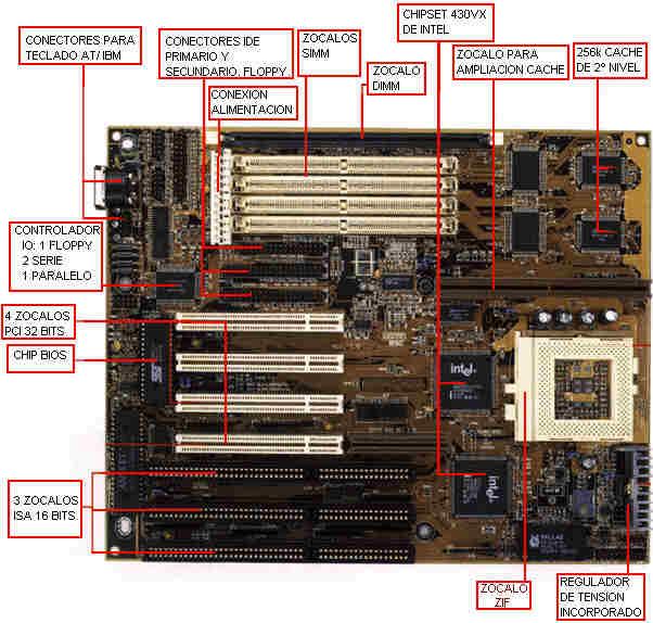
The motherboard is a fundamental component in the computer, since it integrates and communicates all the other devices of the computer. Some plates 486, the 386 and previous ones took the micro welded to the plate, which prevented its substitution. It has been a while since the socket system was adopted to insert the micro. The current ones are called ZIF (Zero Insertion Force or force of null insertion), and they consist of a lever that when raising it allows to enter the microphone without any pressure, then it is lowered and the micro is fastened and all its pins in contact with the plate.
Configuration of the plate.
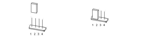
The board has to be configured, for which it has jumpers. For this operation, the manual of the board is essential, since the configuration data are rarely silk-screened on it. You have to specify the type of microprocessor, its voltage, working speed, etc. I insist that you have to have the manual, because this configuration is very different according to the plate. Make sure the correct configuration, since an error in the working voltage or speed can damage the microphone. Here it is important to know that the working voltage of a micro (eg, Pentium 166) can be of the standard type (STD) or of the type called "voltage regulator enhanced" (VRE). This is specified in the screen printing of the micro, where among other things you can read three letters together that normally are three eses "SSS". The first indicates the type of voltage: The "S" indicates type STD ,. If it is a "V", it indicates type "VRE". Recently a type of board has arrived that does not have jumpers, but that is configured by software. Arrange the jumpers according to the manual of the plate for the type of micro that will be mounted. This is very simple, just insert the jumpers on the indicated pins.
Figure 1.2.2. Inserting a jumper in position 1-2
Elements.
The current boards have built-in input-output controller for 4 hard drives and 2 floppy drives (IDE controller) and serial and parallel (IO) ports, while in some 486 and earlier, this device was separated, on a card . That is why among the chips of the board we will find several connectors for flat cable, which are the ones that lead to the hard disk, floppy disk and input-output ports. Lately the "USB" port (Universal Serial Bus or Universal Serial Bus) has been added to the boards, which simplifies the connection of devices to the computer. The DMA memory direct access controller and the programmable interrupt controller are also found on the board.
Here the concept "INTERRUPTION" appears, which is a kind of request for attention to the micro, during his work. The interruptions allow the management of certain resources that need the attention of the processor, but that should not steal time. Periodically, the interruptions are checked by the micro, which spends some time to perform the work requested by the resource, then leaves and continues his work, until the new interruption request, in which he continues doing this work to the resource. This intermittent form of process is not noticed by the user, because it is carried out at a great speed. It is thus achieved, attend to many different things at once without blocking the micro.
DMA channels are shortcuts that are used to communicate devices with memory directly, so that work is accelerated. The DMA controller is capable of moving blocks of data without the participation of the micro.
Another issue is the entry-exit ranges (base IO adress). An example that although not very good, can serve to understand its existence, would be the direction taken by cars circulating in a big city. Despite sharing the streets and using the same or the opposite sense, they all circulate and arrive at their destination appropriately (although traffic is not enough to make this claim). The correct choice of interruptions, DMA channels and range of addresses is sometimes the key to the proper functioning of the computer's devices, especially the cards coupled to the motherboard.
The power connector is double and is usually near the keyboard connector. The power supply has several outputs, of which only two can enter this connector. Attention to the position: putting the two connectors of the source together, the black wires should be together in the center and symmetrically.
The group of 6-8 sockets that can be seen is intended for cards that can be "punctured" in the computer, of which the most common is video, although some plates of higher quality include it among their circuits. These sockets are currently of two types: PCI (usually white), and ISA (black, longer than PCI and separated into two parts). Its function is as I said before housing the cards, which can be video, sound, internal modem, video capture, additional ports, SCSI adapters, network cards, etc.
The sockets are connections to the computer bus, which can be compared to a highway where data travels to and from the micro. The PCI Bus has a width of 32 bits and 33 Mhz of speed, while the current ISA is 16 bits and 8 Mhz. The wider it is, the faster the communication will be, because more data can be passed at the same time, in the same way that a four-lane highway allows more cars to pass than one of two at the same time. Whenever possible, the cards are manufactured for PCI Bus, leaving the ISA type outdated, although some cards (sound cards for example) are still being manufactured for this Bus. Some 486 are equipped with a Bus called VESA, 32 bits, whose socket is easy to identify since it is formed by an ISA, plus an extension in the back. This Bus disappeared quickly, since the PCI, although also of 32 bits is more efficient.
Another important member of the motherboard is the BIOS (Basic Input Output System or Basic Input-Output System). It is a chip that contains some very basic programs that manage the basic operations of the computer as well as its configuration. The BIOS is at the lowest level, below the operating system. It can work only with the micro, RAM and video card and is the software base for the computer to work. The configuration of the computer is managed by it and stored in a memory of CMOS type, so as not to lose information when the computer is turned off, it is powered by a small lithium battery or battery included in the motherboard.
Other sockets that are on the board are those of RAM. There are currently two types: Sockets for SIMM (Single In-line Memory Module) modules with 72 contacts and sockets for 168-contact DIMMs (Dual In-line Memory Modules). The trend is the DIMM module. These sockets are grouped in BANKS, so that one or two sockets constitute a bank, depending on which plate. There are usually four SIMM sockets, plus one or two DIMMs. It is important that the board has DIMM sockets, which happens in the case of a VX, but not in the HX (at least for now). There is a complete section for the memory later.
The pins for the connection of the Reset button, HD light, and speaker are the last point to highlight. The manual or the plate itself specifies which is each, although it does not generally indicate the polarity, something that must be respected in the case of LEDs, but it is not worrisome, because if the polarity reverses, nothing will happen, except that the light do not shine Change the polarity then.
The external cache memory (or second level) is a small memory (256 or 512 k) and fast, located structurally close to the micro and used by it very often. It can be welded to the base plate, welded part and a base to add more, or all in baseboards, according to the plate. This memory speeds up the work of the micro, providing quick access to frequently used data or data that are expected to be used immediately. Observe the following example:
A mechanic will repair an engine, and is prepared by bringing a small table with wheels (frequent in the workshops) to the vehicle and placing in it the tools that will be used repeatedly or those that will be used for the first part of the work. This saves you having to go to the tool board (which is fifteen meters away) every time you need one. Something similar is the function performed by ANY memory called cache.
Pentium boards do not work for the Pentium Pro or MMX micros. You have to use others that are similar, but use other chipset. The latest novelty in motherboards is the ATX standard, which is nothing more than a new arrangement of the elements of the plate in order to improve ventilation and make more comfortable work on it.
All the components are linked to the motherboard, but I'll talk about them later, in its corresponding section.
The PLUG AND PLAY system (plug and play).
This system appeared in order to facilitate the incorporation of cards and other devices in the computer, automating the choice of IRQs, range of addresses, etc. This is a bit complicated, which leads to errors in the choice of parameters, especially to use some IRQs that are already being used. This system has come to call PLUG AND PRAY (plug and pray), the complexity of correcting their errors, especially when the automatic being, is obstinate in using invalid parameters. The current motherboards are of this type, and the cards too. These last ones do not have Jumpers (those that are not PLUG AND PLAY, yes), and their configuration is done by software, instead of using said Jumpers.
A card that is not P & P, can be installed on a motherboard that is, and vice versa. The only thing to keep in mind, is that the configuration if you have to touch it, will be done by the jumpers if the card is not P & P, and by software if it is.
Mounting.
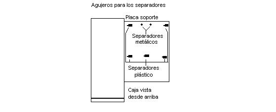
The plate is sensitive to static electricity. Remember what was said in the introduction. The assembly involves placing the base plate on the metal plate on the right side mentioned above, which will have been disassembled and left in a horizontal position. Be careful not to short-circuit any element of the plate with any metallic object such as the support plate itself. To do this, the box is supplied with plastic pieces that end at one end in a tip, and another on a base, and serve as a separator, so that the base plate does not touch the metal plate of the box. Bring the motherboard close to the support plate, so that the keyboard connector is towards the back of the stand. Look at the holes in the two plates. Those whose position coincide, will be those who carry the piece of separation. Install as many as possible, introducing the tip of the pieces in the holes of the base plate by the bottom of this. Note that on the side of the base plate where the keyboard connector is, there are one or two holes located near the center. These are intended for the fixing screw. Mount the metal spacer on the support plate (it is screwed), and once the base plate is in place, screw it to the metal spacer using a screw with insulating washer supplied together with the screws of the box. This drawing shows the situation of the support plate once it has been deployed and the holes and holes for the separators.
Figure 1.2.3.
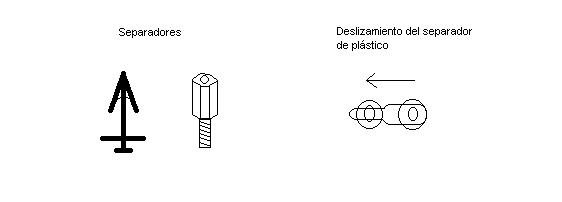
To attach the plastic spacers to the support plate, they must be slid. This image details the spacers and how to slide the plastic ones through the hole:
Figure 1.2.4.
Once the base plate is fixed to its support, you can close this side of the box by placing the support plate in its place of origin, but if you want to work more comfortably, I recommend that you install the micro and RAM before closing, because Then you will have less space to do it. The instructions for placing the micro and memory are in their respective points. Observe also the display. Depending on the side in which it is located, it will be necessary to prepare it already or later. Make sure you do not close access to anything you need to touch later.
Source and Credits to: https://html.rincondelvago.com/reparacion-y-montaje-de-ordenadores.html