Calculation of the number of plates of a rectification column. (Part -2)
Good day Steemit community. Today I give continuity to my previous post of calculating the number of dishes in a rectification tower. Then the steps to follow to execute this process.
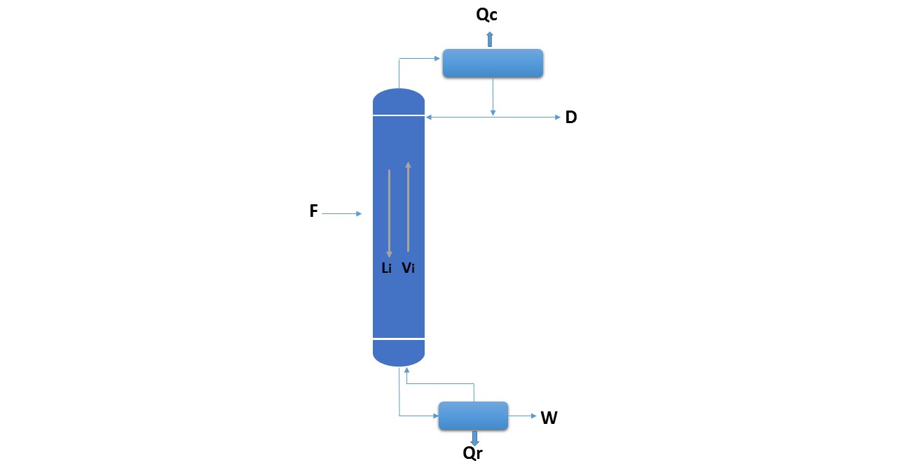
Figure 1.
General method to determine the number of plates above the feeding plate:
As will be observed in the previous publication, the general method to determine the number of theoretical plates above the feeding plate consists of:
1st step: locate the point corresponding to the current in the system diagram V1
2nd step: as V1 is the current of steam that leaves the plate 1 and that must be in equilibrium with the liquid that leaves it (L1), by means of the equilibrium line that passes through V1, where it intercepts the curve of liquid is located at L1.
3rd step: located point L1 an operation line is drawn between it and point D ', where this line intercepts the vapor curve will be located at V2.
4th step: repeat the process until some equilibrium line cuts the line joining D 'with W', as shown in Figure 2.
Each line of equilibrium represents a theoretical plate.
Summary: the straight lines joining the points Vi + 1, Li and D 'are called operation lines and join the points corresponding to the input and output currents on the same side of the plate and the equilibrium lines join the points Vi and Li , the vapor and liquid streams that come out of the same plate and are in balance with each other.
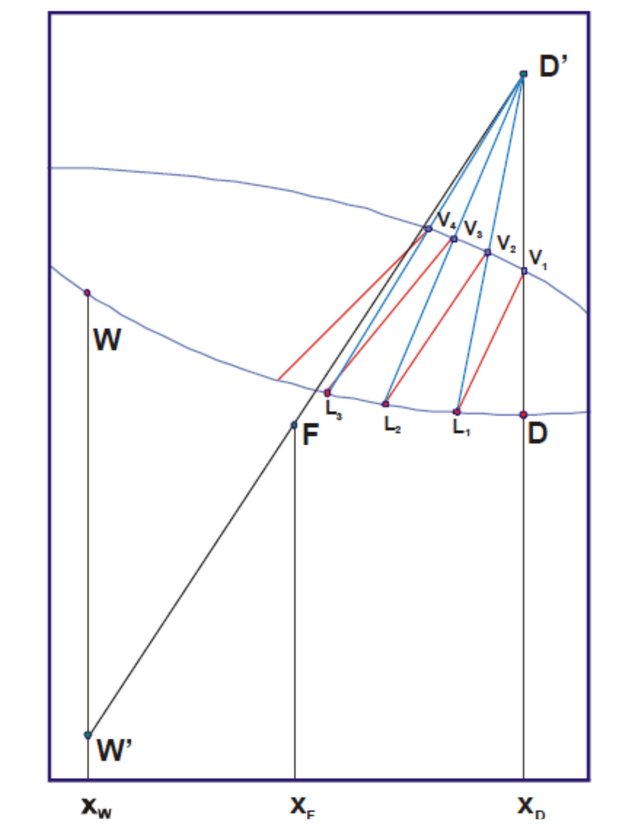
Figure 2.
Balance in the reboiler:
The last plate of the column will be called plate m (m is the total number of plates in the column). As it will be seen in Figure 1, the liquid that leaves this plate (Lm, which is a saturated liquid, at its boiling temperature) is sent to the reboiler where it vaporizes in part, producing a vapor (which will be designated as Vm+1, since it is entered by the bottom of the plate m) and a liquid (W, which leaves the bottom of the column as saturated liquid). Making the balances around the reboiler:
Lm = Vm + 1 + W
(mass balance)
Lm.xm = Vm + 1.ym + 1 + W.xW
(component balance)
Lm.hm + QR = Vm + 1.Hm + 1 + W.hW
(energy balance)
If it is considered that all the heat delivered to the reboiler was delivered to the current W:
Lm.hm = Vm + 1.Hm + 1 + W.hW - QR
Lm.hm = Vm + 1.Hm + 1 + W (hW - QRW)
As seen in Figure 3, the three collinear points are:
Lm (hm, xm)
Vm + 1 (Hm + 1, and m + 1)
W '(hW - QRW, xW)
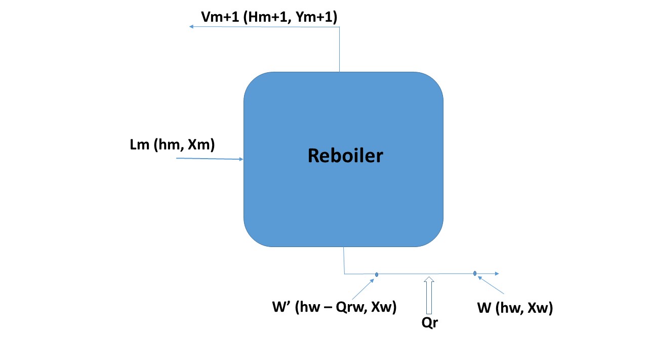
Figure 3.
In the reboiler there is a partial vaporization of the current Lm, so the vapor and liquid streams that leave it (Vm+1 and W) will be in equilibrium with each other, so this equipment is considered as if it were a theoretical dish more.
Figure 4 shows the three collinear points joined by an operating line.
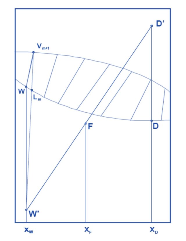
Figure 4
Balance on a generic plate g under the feeding plate:
Now suppose a generic plate g that is located between the feed plate f and the last plate m, as shown in Figure 5.
Lg-1 = Vg + W
(mass balance)
Lg-1.xg-1 = Vg.yg + W.xW
(component balance)
Lg-1.hg-1 + QR = Vg.Hg + W.hW
Lg-1.hg-1 = Vg.Hg + W.hW - QR
Lg-1.hg-1 = Vg.Hg + W (hW - QRW)
(energy balance)
The three collinear points are:
Lg-1 (hg-1, xg-1)
Vg (Hg, yg)
W '(hW - QRW, xW)
This indicates that below the feed plate the operation lines are joining the points Vg, Lg-1 and W 'as shown in Figure 6.
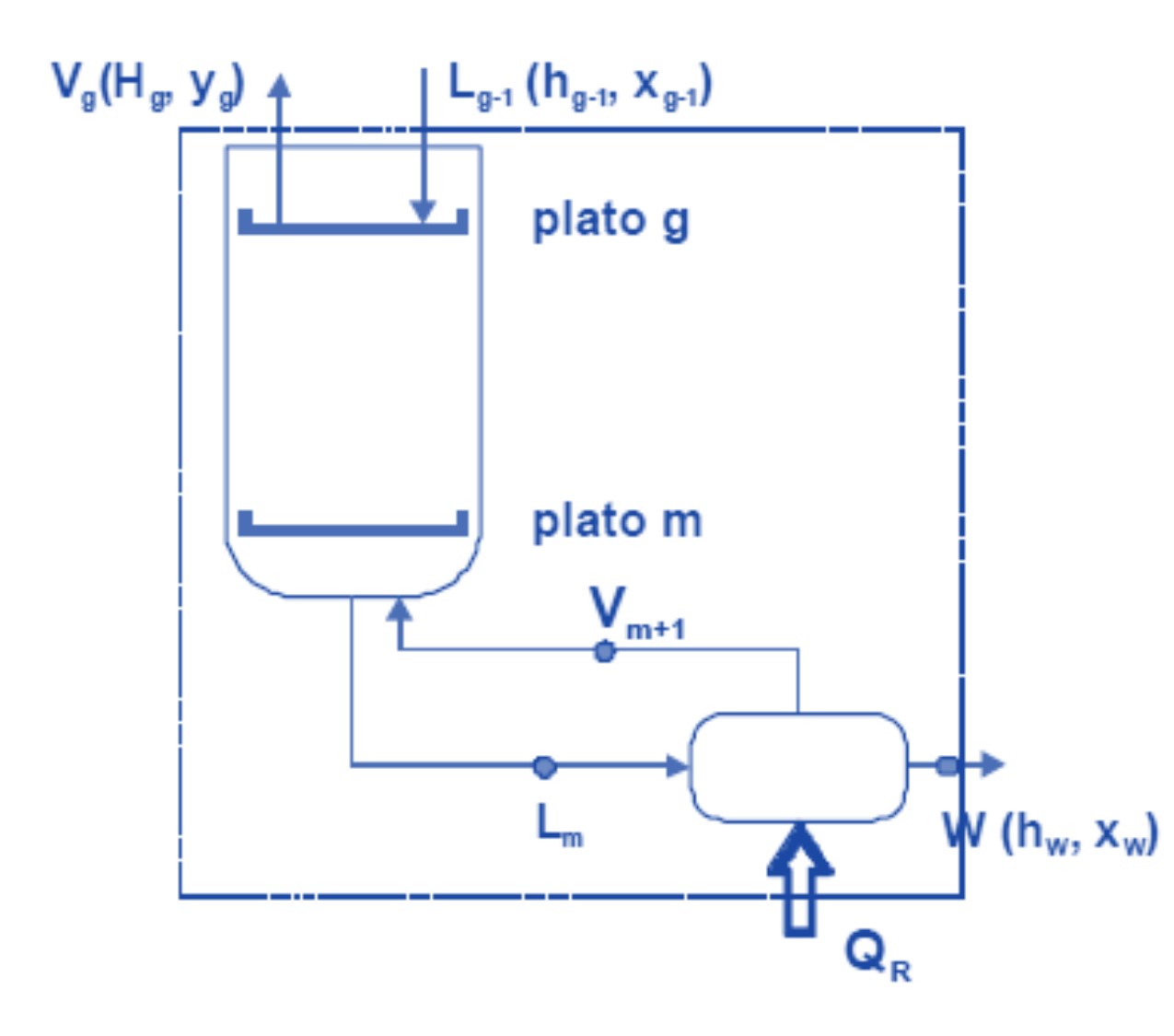
Figure 5.
Determination of the total number of theoretical plates:
To determine the total number of theoretical plates of the column (given the data of the feeding conditions, the concentration of the top and bottom products and the external reflux ratio) the following steps are carried out:
1st step: the compositions of the vapor and liquid streams that leave each plate above the feeding plate are determined.
2nd step: when a balance line crosses the main line of the column joining W ', F and D', the compositions of the vapor and liquid streams below the feeder plate are determined. Each line of operation is a theoretical plate (including the reboiler).
This method can be seen in Figure 7.
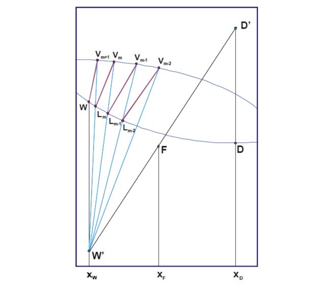
Figure 6.
If, when the successive balance and operation lines are drawn, the last equilibrium line does not coincide with the point corresponding to W, the calculation will have to be made again by varying the value of XW.
In the case shown in Figure 7, the column has 7 plates (the reboiler would be the eighth).
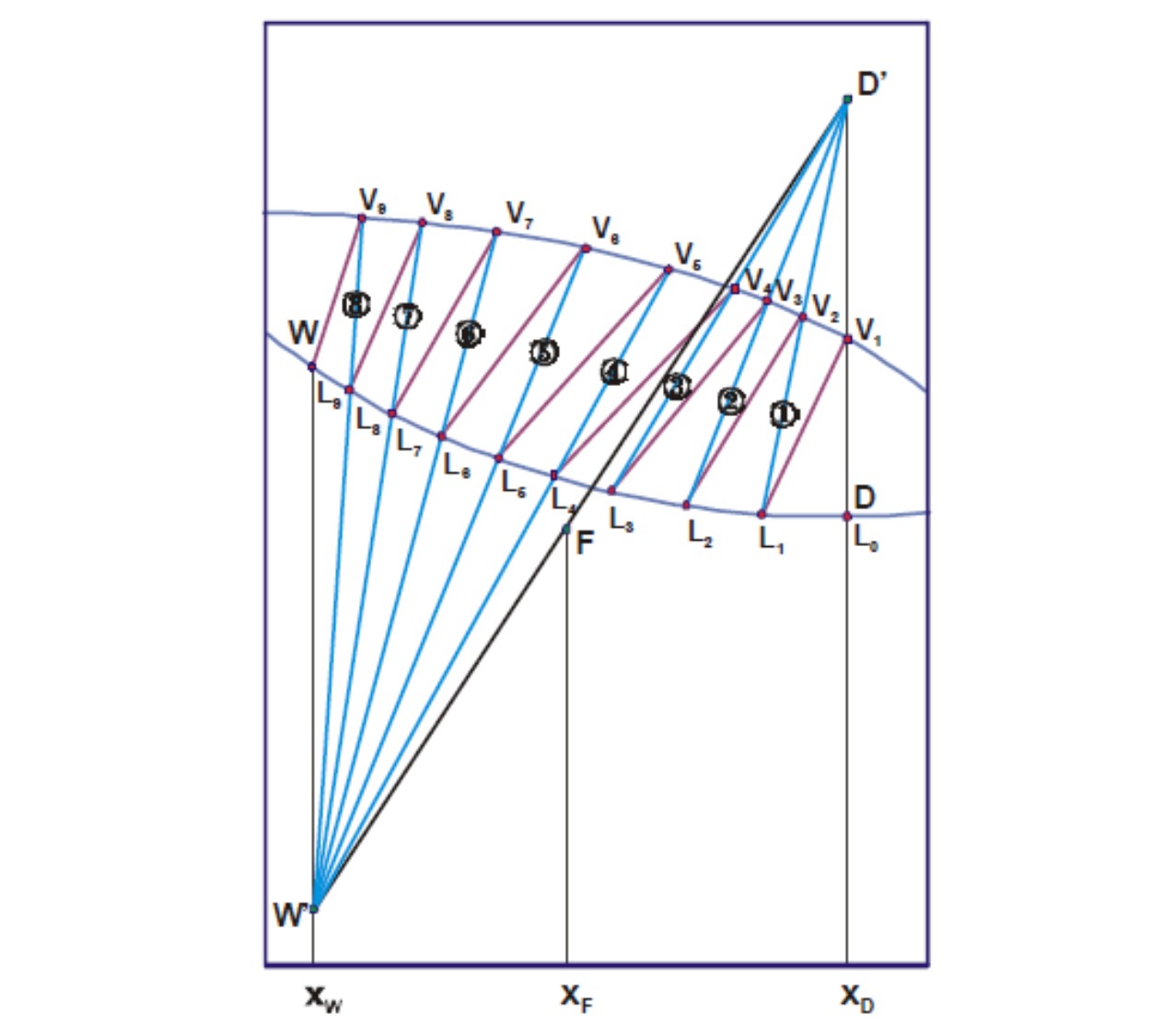
Figure 7.
Situation of the feeding plate:
Figure 7 represents the graphical solution for the determination of the number of theoretical plates needed to effect a given separation. It is seen that three theoretical plates are necessary above the feeding plate; the fourth theoretical plate is the feeding plate, since as it is observed in the figure, the point L4 (h4, x4) is united to the point W '(hw - QRW, Xw) instead of being it to the point D' (hD + QCD, xD). It is not necessary that the feed enters through the fourth theoretical plate. If the feeding is introduced below the fourth plate, this plate is in the section located on the feeding plate and as will be explained in Unit Unit II, a greater number of theoretical plates will be necessary if the feeding is done below the fourth dish
Similarly, if the feed is introduced above the fourth plate, it would be found that a larger number of theoretical plates would also be necessary to carry out the separation. From the previous discussion, it is deduced that the number of theoretical plates necessary to effect a given separation, in which the terminal conditions and the reflux ratio are fixed, is not constant and depends on where the feed is introduced. However, there is a situation of the feed plate that gives the minimum number of theoretical plates needed, with a set reflux ratio, and this situation (called "true feed plate) is the one that should always be used.