Controlling the electric power factor in electric power transmissions: Capacitors
Hi everyone :)
Potential energy can be statically stored in an electric field by using a capacitor which is a passive two-terminal electrical component. The capacitance is a measure of how much electrical charge "Q" the capacitor can store per voltage "V" and is important if we want to compensate our reactive voltage. The SI unit of the capacitance is farad ("F"), named in honour after Michael Farraday. A farad = 1 C/V (1 As/V) -> a capacitor charged with one volt can store one coulomb. Less distance, good dipole formation in the dielectric and bigger plates -> higher capacity. We can easily proves this with the following formula:
C = ε0 * εr * (A/d) -> e0 is the dielectric constant = 8.85*10^-12, er the specific number for the material, A the area of the plates and d the distance. If all values stay constant and
A increases -> higher value (e.g. 1/2 < 5/2 )
d decreases -> higher value (1/2 > 1/4)
εr increases -> higher value ( 1*2 > 1*1)

As you can see on the picture, a simple capacitor consists of two conductive plates, separated (distance "d") by the dielectric which is an electric insulator that can be polarized by an applied electric field and (depending on the material) has a unique, relative permittivity. One of the two plates accumulates the positive, the other the negative charge. The plates and the dielectric can be arranged parallel or around each other.

This is the symbol for a fixed capacitor
You may have already seen a capacitor like on the picture below. We find them in many electrical devices such as motor starters, flash cameras, radios or defibrillators and even in particle accelerators. Capacitor are also used for signal coupling, to prevent data losses while the battery of a device is loading and are part of the voltage maintenance in the power grid. Different types are available, inter alia, ceramic, film, paper, super and electrolytic ones, always based on their factors. For example, electrolyte capacitors are used when large capacitance is required, having a thin layer of oxide for the dielectric.

Important note: A capacitor can still be charged even if the device wasn't connected to a power supply for a longer time so please don't touch electrical contacts if you don't know if it is dangerous or not!
Issue
In industrial productions, a high amount of reactive current appears because machines, powerful electric engines or transformators lead to a high amount of total inductivity. This issue leads to negative effects such as higher energy costs because the reactive current isn't captured by normal electric meters. Power plants produce more energy than they get paid for so prices are raised to compensate ( :D) the costs. It also unnecessarily stresses the power grid & it's stability without transporting energy as the apparent power a device is taking, isn't equal to the real power we can transform into other forms of energy e.g. mechanical, chemical or thermic energy. Reactive power is just oscillating between the device and the power grid.
Through a Pythagorean relationship, the apparent power can be described as S = √ ( real power² + reactive power² )

The apparent power, the vector sum of reactive and real power. Unit of real power "P" is W (watt), of reactive power "Q" it is var (volt-ampere reactive) and of apparent power "S" va (volt-ampere)
To solve this problem, companies own capacitors that proportionally compensate the inductive phase swift by activating or deactivating them. Big fabrications have a counter for the reactive current, so the amount which they wouldn't compensate is a avoidable cost factor. Capacitors can be linked to one, two or a group of devices with the ability to compensate the total reactive current of them. But how does this whole compensation work?

An example of how a compensation system can look like. Reactive current compensation is getting done on nearly every scale, from lamps to synchronous generators in a power plant.
Explanation attempt:
Direct current
Alternating current is the product of voltage and current: P (power) = V (voltage) * I (electrical current) and can be described as an sinus function. Both of the voltage and the electric current sinus function can have the same maxima and minima, if their phase is the same, meaning the product of V * I is either zero or equals a positive value ( -x + -x = x), -> no energy flow reverse. The result of the two sinus functions is always a positive value and can be described by the red line below:

The result of the two sinus functions is always a positive value and can be described by the red line
Alternating current & voltage
If the load is purely resistive, the sinus function of the voltage and the one of the electrical current reverse their polarity at the same time. The opposite would be a 90° phase shift, ending in a 100% reactive current and no energy transfer because two quarters of each cycle, the product would be positive but for the other two, it would be negative -> as much energy flows in as out -> no net energy flow. In reality, the shift factor calculated with is cos α:
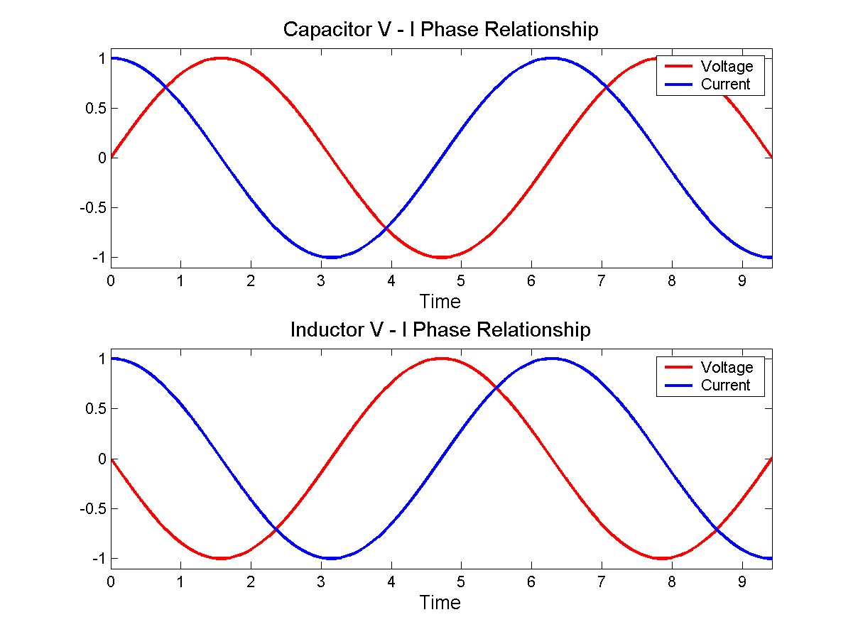
As you can see on the upper illustration, at the maximum of the voltage, the current is on the 0 level and vice versa. Imagine it like this: The capacitor is like a concert with people streaming in until the space is 100% percent full -> red voltage sinus function. The blue cosinus function for the current are the vistors in my model. If the concert is empty, people run inside without getting stopped. Now the more people come in, space is getting reduced permanently and it is harder to get through the crowd. After every visitor is inside, no more people can stream inside -> current = 0 and the concert is full -> voltage = 1. You can see this on the graphic from number 6 to 7 on the x-axis.
The use of capacitors
The complex power is defined by the vector sum of the active and the reactive power. The calculation would be: S = √ ( V² * I² ). In our case, we have a phase swift with, so we have to look how much real power our e.g. machine really needs. Therefore, P = V * I *cos φ is the equation we have to use. Whereas at the capacitive load "I" is faster than "V", now there is a delay from "I", so the voltage is faster than the electric current. At the time the inductor takes current, the capacitor releases it, resulting in an elimination of the two functions -> no reactive power left.
An easy example:
An easy way to compensate the reactive current is to create a parallel connection between an inductor and a capacitor:

This is a classical power circuit of a flourescent lamp which needs an inductive ballast to start and run it over a certain time. Having an inductive ballast, reactive current appears. That's where the compensation steps in: Because of the parallel connection, the system behaves resistant and compensates the power until the reactive power is zero and only the real power is left. It is as easy as -1 + 1 = 0, no reactive current is left. After this, the power can be calculated with the normal equation P = I * V again.
Calculation example
Let's say we take 230V, the network power of 50hz and a lamp that needs 3.45A to work. It's real power is 450W and we know the apparent power:
S = U*I
->230V * 3.45A = 793.50VA
To calculate the reactive power we use
S = √(S^2 - P^2)
-> S = √((23o V * 3.45 A)²) - (450W²) )
= 653.56var
As we want to now what capacity (C) our capacitor has to have, some more steps are needed:
->P = U² / R
-> Q = U^2/Xc
-> Xc = U^2/Q
-> Xc = 1/(2* π *f*C)
-> C = (653.56var)/(2* π *50Hz*(230V)^2) = 3.9326e-05 As/V
= 39.326µF
Adding a capacitor with about 40 F will help us to prevent reactive current in the lamp circuit - Awesome, isn't it?

Thanks for reading and have a nice day :)
SourceTexthttp://www.melitec.de/fileadmin/kundenbereich/PDFs/Wirk_Schein_Blindleistung032015.pdfhttps://en.wikipedia.org/wiki/AC_powerhttps://www.vh-buchshop.de/media/upload/file/leseproben/143422MS.pdf (translated)https://en.wikipedia.org/wiki/Applications_of_capacitorshttp://kondensator.eu/die-verwendung-von-kondensatoren/ (translated)https://www.elektronik-kompendium.de/forum/forum_entry.php?id=50182&page=528&category=all&order=timehttp://elektroniktutor.de/analogtechnik/kompens.html (translated)http://www.elektrotechnik-fachwissen.de/wechselstrom/leistung-wechselstrom.php (translated)https://www.efxkits.co.uk/different-types-of-capacitors-applications/https://de.wikipedia.org/wiki/Kondensator_(Elektrotechnik)#Energie-_und_Ladungsspeicherhttps://www.vh-buchshop.de/media/upload/file/leseproben/143422MS.pdf (translated)Pictures