ArduinoProject: Make a Temperature Controller
What’s up guys? I am @bramvbilsen. In this tutorial we're going to be making a temperature controller. Which controls the speed of the fan or controls when the fan turns on or off, via a temperature sensor.
Requirements for this project
- Arduino UNO
- Breadboard
- 10K Thermistor
- Positive & Negative rails
- wire
- Portable fan
- Arduino IDE
- BJT Transistor
- Mosfet Transistor
Resources for this project
So you can actually use that temperature sensor to put it on a heat sink or in some type of an environment. Where you want to have this font, this fan. I'm actually respond to the temperature change.
So today we're going to be doing this, using a thermistor. So we're going to build a voltage divider circuit there, it's very simple. we'll look at an actual little 92 temperature sensor package. And we can do it with that as well. But for this one, we're going to be using a thermistor. So let's get right into it.
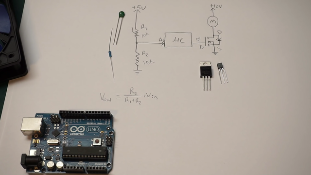
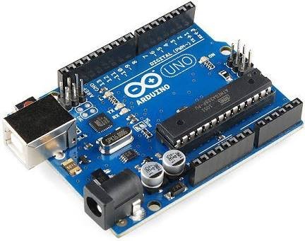
Alright guys, I just want to show you, how we're going to set this up. So we're going to be using an Arduino Uno for this.
You can use just about any Arduino board. They all work. They all have pulse width modulation and the have analog input. So it doesn't really matter. And so essentially what we have here is just a simple voltage divider network, right?
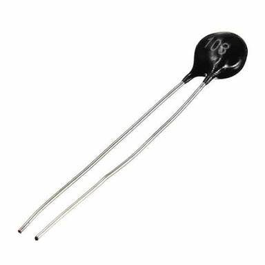
And so I'm using a 10K thermistor.
If you don't know how thermistor work, you don't anything. This is a negative, a temperature coefficient device. So an NTC device. Which means when this device heats up, it's resistance is going to go down. So this resistance is nominal. I think around 25c at10K. So if you go, if it gets harder than 25, see this resistance is going to start to decrease and you can see our voltage dividers can start to increase.
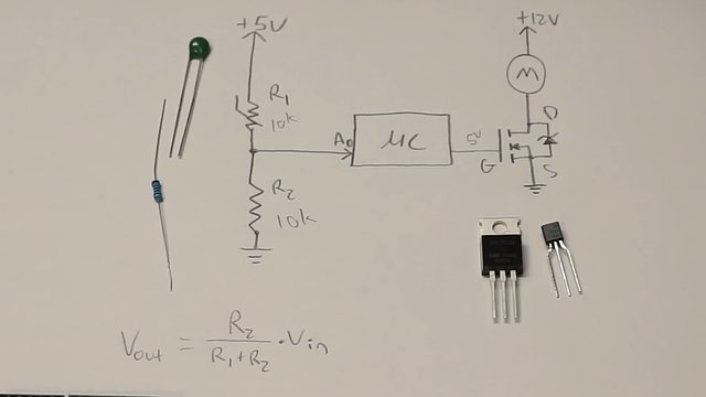
Okay? And down here I just have a fixed 10K resistor. That's this guy right here. And it goes down to ground. So, normally if these were both 10K. Obviously this is going to always be a fixed value. But if this was at 10 we'd get about two and a half for two year, right? This is from our Arduino. And so as this device gets hotter, it's resistance will go down and voltage will go out or I will go up in the Arduino, read that.
So we don't really need to modify this too much. I mean you could put a potential here. If you wanted to kind of like tune it. But the good thing about using an Arduino, we can really do a lot of that. I'm handling, we can process this voltage. And do whatever we want with it in the order we know we can use it to fan speeds linearly.
DESCRIPTION
We can set our own kind of like an equation to deal with this. We could also set ranges. So we could say if the temperature is in this range, turn the fan on 25 percent. If it's in this range, tread on 50 percent, 75 percent or whatever you know. Or You could just use it as a simple switch. You could set a threshold and tell it when to turn the fan on or off. There's so many things you could do. There's an unlimited amount of things you can do to control this and that's really all going to be defined in our software. So we don't miss this. The good thing about using the Arduino is we don't really have to worry too much, about fine tuning this resistor network or anything like that. And just so I thought I'd show you guys real quick. This is the formula for this voltage divider networks.

FORMULA
So v out is the point that's going out of resistor network and into a our microcontroller analog input. So this is gonna be a zero in our case. So I'm going to use analog input zero and the output voltage is going to be equivalent to two over R. One plus r two times a val. In this is just without a doubt. you have seen this as just a voltage divider equation. So just for a simple voltage divided, this is what it how it works out to be. But you'll notice I'm R one is on the bottom, So it's inversely proportional to that. As our one starts to decrease our overall voltage, since it's on the bottom is going to increase, output voltage is going to increase. And so that's how we're kind of basing our software.
If you have a PTC device, so positive temperature coefficient, it's not a big deal. You'll just negate everything in software, right?
You could just put that on the bottom and it would do the same as well. So you could flip these if you had a PTC device. So the actual Arduino itself is not powerful enough to drive a fan or some device like this for a couple of reasons. For one, notice it's at 12 volts. So this fan is at 12 volts. You might be dealing with a 12 volt fan. The fan doesn't matter. It's not really going to drive it unless it's a fibo fan. And even if it is a five volt fan, the current output of an Arduino is like maybe, you know, I don't even know if it's less than 100 milliamps. Probably I don't know what I have to look at the data sheet again for the actual chip, but it's really small.
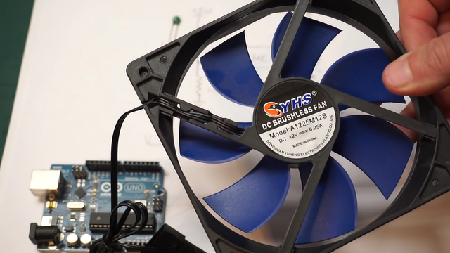
I can guarantee you it's probably less than a hundred million. So it can't drive very much at all. And so to handle that. we have to actually integrate it with some type of a transistor. And I really recommend you guys use a mosfet transistor because they're the simplest to use. You can use a BJT. If that's you have lying around. You can use an NPN or PNP. It doesn't matter. But then you gotta worry about. Your actual gate current and you got to do a little bit of, some extra work there as far as bypassing that transistor goes. You gotta put some resistor network in there. So we'll talk about that in other tutorial. But I'd recommend just stick with Mosfet if you can. So here's, what's going on. This mosfet allows us to drive a higher current with these Arduino. This Arduino can't really drive a high occurrence on. It’s own and allows us to interface with a higher voltage.
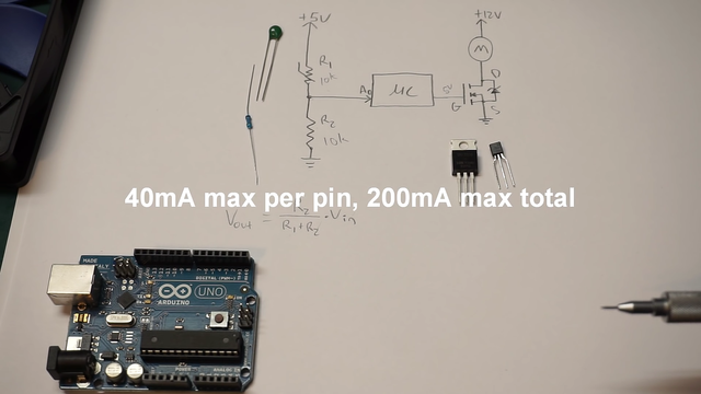
So basically this whole thing is the mosfet. It has little zener built in it. So this is a little protection diodes. So this is not some external component. And so the gate is driven directly by the Arduino. So the mosfet itself is able to just control device. There's really no current flowing through here. We don't have to worry about a resistor in series a between a microcontroller and the Moskva. It doesn't really matter. So we can drive the gate directly. That's kind of Nice. It simplifies it a little bit. The source goes down to ground. This is an n channel. This is for an end channel Mosfet for a p channel. It will be completely different. You also have to negate it and software. If you're using A P channel. But the drain goes up to the negative terminal of our motor that we're trying to spin or the fan, right?
So the negative terminal of our fan and the other side of the fan goes straight up to r plus 12 volt. whatever rail that we're working with.
So that's how it works. It's pretty simple. And so for this tutorial, I'm going to be using a two and 7,000 device. So that's this guy right here, and it's only rated for 200 Milliamps. So don't bust my balls on this. That you're playing along at home. I know it's not really quite the amount of current that we should be doing. We should have a little bit higher than this. Because this fan has a 250 mil amp rating on it. So it says actually draws up to 250 milliamps. But I think we'll be fine for this. You could use something like this or if you're driving a higher power device, you could use some top 20 package or whatever.
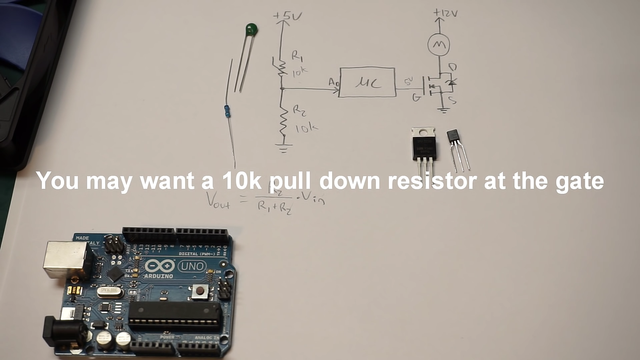
It doesn't really matter as long as. It's rated for the voltage and current that you're working with. One thing that is very important that I will say, you have to look for in your device is the actual gate threshold voltage.
So you want to look for the maximum threshold voltage that is saying the maximum voltage. It will take to actually turn on the gate of your n channel Mosfet or p channel Mosfet or whatever. And in the case of this 200, 7,000 is about three volts. So what that's saying is it will take no more than three bolts to actually turn on the gate. You don't want to look at the minimum. You want to look at the maximum and it should be five volts or less. If your maximum gate threshold voltage is above five volts, there's a chance that this microcontroller won't put out a high enough voltage to actually turn your gate on.
All right, here's my setup.
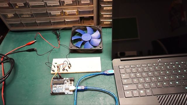
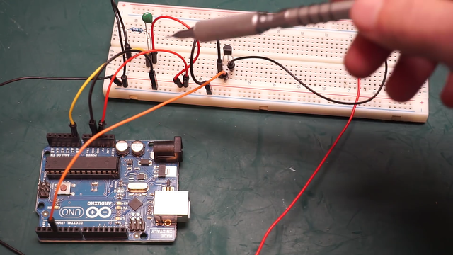
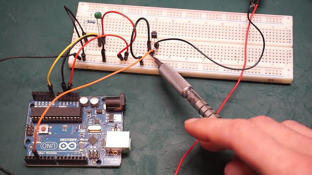
It's wired just like I showed you on that schematic. So it's wired the same. But I just want to draw your attention to a few things here. So here's the Arduino, I haven't hooked it up yet. And this is our 12 volts coming in or whatever else you're going to be working with for your fan. It's our higher voltage coming in. And what I want you to notice is that first off, the positive lead of our higher voltage supply. In this case, our 12 volt supply doesn't even hit our breadboard. Nothing over here is touching 12 volts at all. So don't even run 12 volts into your breadboard. No need to do that, right? 12 volts go straight into our fan, just like the schematic.
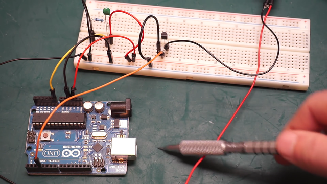
This circuit really is just switching on and off our ground path to the fan is all it's doing.
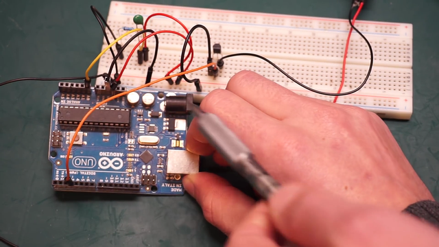
So you'll notice our ground goes into our breadboard and I'll show you guys that are more close here in a minute. And then our output of our end channel Mosfet goes out to the ground on our fan, to the negative side of our fans. So that's how that's working. So closer up. First things, I want to realize here that the ground of our Arduino, so the ground on there. Do we know is tied to the actual ground on the breadboard. That is tied to the ground on our power supply. So our higher voltage ground and our ground on from our Arduino five volt supply are tied. They are tied so that we can have the actual current flowing for are signals. It is important that, those grounds are tied. Nothing will be damaged from that. Just don't tire higher voltages to your lower voltages.
Obviously that's why our 12 volt doesn't even hit this breadboard. So going into the Arduino, Here's our a little voltage divider network over here. So we have bibles coming from the Arduino going into the positive rail on this breadboard.

Thermistor is getting one side of it is going into the positive rail. The other side goes to that kind of voltage divider point where those two resistors connect and fixed 10K as going to the ground. So to ground, just like the schematic. The output of our voltage divider network goes through this yellow wire into a zero. Zero is getting the output of our voltage divider network. And then our mosfet. It's a source is tied to ground. So that's where it's getting all of.
It's kind of like power from if you will. And then the actual gate is going straight from this orange wire into Arduino. I'm running that on digital pin three. you can run it on any digital pen you want. Just make sure it is a pulse width modulation, depending if you want to do pulse width modulation. So we can't do pulse width modulation unless you use a pws pin. And on a lot of Arduino boards, they either say PWM or they'll have that little squiggly line right there. Next to the actual number that indicates it take PWM pin. So you can actually use it for PWM. And then the drain of our little Mosfet here is going out to the negative side of our fan. That's how this whole guys wired up. So let's go ahead and hook it up and I'll show you what we need to do in order to get this thing working.
CODING
Alright guys, I have the board hooked up here and we're going to run some code.
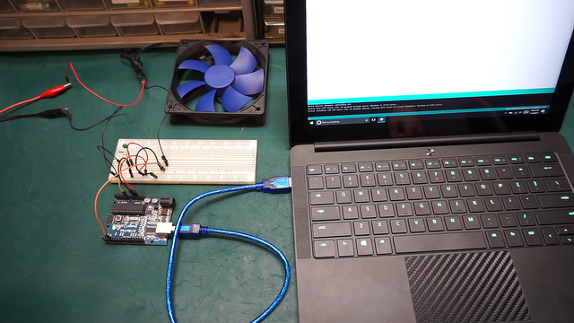
I'll show you that real quick here. But before I do that, I just want to let you know that we are actually using a different board now. I'm not using the uno anymore. I'm using the Arduino do a menu and off. Just you don't freak out about that. Change on my Arduino. Uno was giving me some issues. It wasn't wanting to communicate with my computer for some reason. So I use this board instead. it is pretty much identical to the Arduino Uno. All the peanuts and everything are exactly the same. There's really no difference. I think just the surreal communication chip is different, but besides that it'll operate exactly like an uno. So there's really no change. I just wanted to let you know that, what code we're running here.
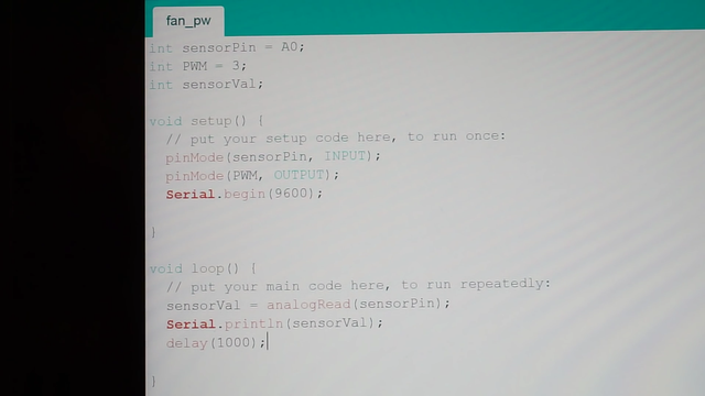
This is not the actual final code. But this is a process. That we need to do in order to kind of get an idea. Where our sensor or our voltage divider is going to sit in the range. That we're going to be operating in.
Let me show you the code real quick first. Here's the sensor pin. I just kinda did. All of our declarations are pin declaration. So there's sensor pin is on analog zero PWM. That's our output going to our transistor. This is unpinned three. So this was from our voltage divider network. And I just made this value called sensor val.
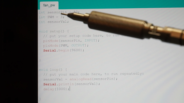
We'll see that in a minute. I didn't actually initialize it by, just kind of declared that there. And then in our setup really easy. All we have is our pin modes.
So I said the sensor pin, that is our voltage divider is an input. So it's going into the analog input obviously. And then, pinmode PWM output. So that is PWM pin driving our fan. It is an output. And the purpose of this serial begin here is. We're going to actually look at a 10 bit value coming from our voltage divider network from our actual thermistor sensor. And I'll show you guys why that matters here in a minute. You will see pretty fast. But, in our loop, here's what's going on. We have value that I declared before sensor value. And I'm going to say the sensor value, this is our 10 bid value is equal to the analogread of our sensor pills. So all this do reading the actual, the voltage on our sensor pin. And it's putting it into a 10 bit a digital value that we can read.
Then what it's gonna do. It's going to take that cereal dot print line. And it's going to print out that sensor value and I put a delay here for a thousand milliseconds. Every second it will update this. And what it's gonna do. It's just going to read the actual value coming out of our voltage divider network, put it into a 10 value. It's going to print that on our screen here. And we'll see those actual values coming on our screen. And this is really important to find the lower limit of our sensor. And the upper limit depending on what you're going to be operating the sensor. I'm gonna go ahead and open up the serial monitor right here.
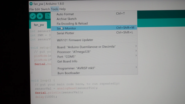
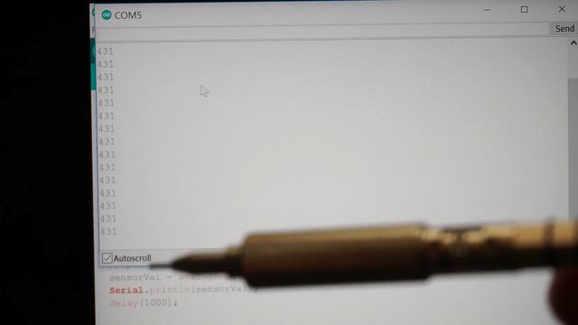
What this is going to be printing out is our actual 10 bit value from our voltage divider network.
So this is kind of the temperature of sensor. Obviously it's not the temperature but showing us right now. Because my sensor is just sitting there on the breadboard. It is the lower limit or whatever would expect to be kind of the ambient room temperature right now. This sensor sensor would be putting out our voltage divider. We'll be putting out at this ambient temperature and we'll actually get to see this. I'm going to write this value down right now.
400 and 31. If the room was a little bit cooler, our temperature was a little bit cooler, it'd be a little bit lower than this. So let's just say it's going to start at like 400 actually to keep it simple. What I'm gonna do. I'm going to heat up my sensor and I want to see kind of that maximum value.
I want to see the upper limit of our sensor. Where I want my fans to go to 100 percent. So what temperature? I would want my family to go to 100 percent. What I'm going to do. I'm actually going to take my soldering iron and I'm just going to place it on the sensor. And you will see these actual values start to go up guys. So I have my iron here and I'm going to touch it on the sensor, you can see it's jumping up.
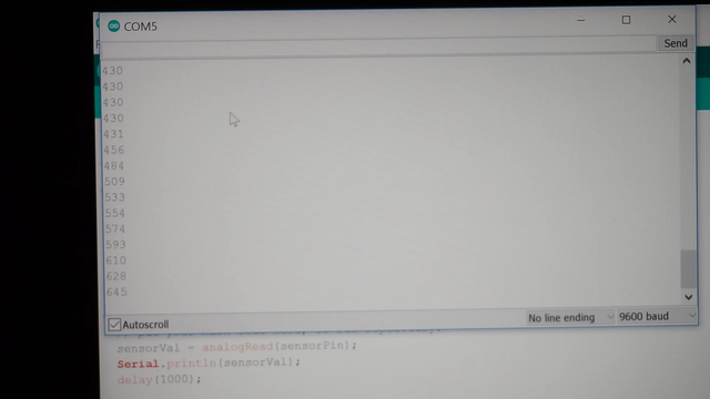
I only have it updating once per second. I don't need it to update, 10 times a second you can by changing that delay value updated faster. But really I just kinda want to see where it speaks out at because I'm going to use this value as my 100 percent for my fan curve.
And you can really set your fan curves however you want. So I'm seeing it's kind of starting to slow down here. I'm going to go ahead and say we'll just say 800. My maximum value. So at 800, I want my fans to be at 100 percent. So my lower value is going to be 400, in my upper value is going to be 800. And so like I said, that's really going to depend on your application. You might not want your product to get as hot. You might want your fans to kick in at a higher temperature. And you can take these values. You can use them to adjust your PWM linearly. You can use it with if statements to set kind of condition. So if it's in a certain range of temperature, you can pulse with modulate your fan output to a certain amount.
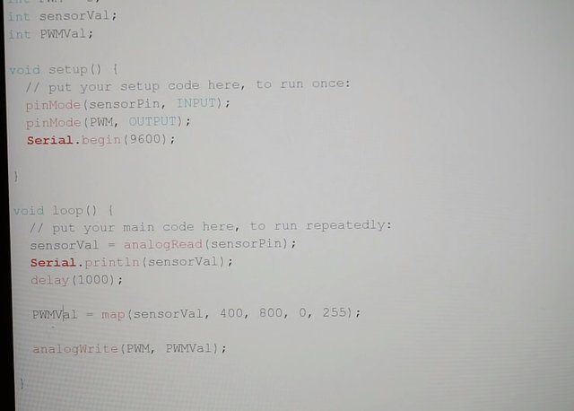
So you could say it's 25 percent, 50 percent, 75 or 100 percent or you can just use the threshold. I mean, all right. So here's the rest of the code.
But like I said, there's many, many different ways of approaching this. This might not be the best for your case. So definitely it's going to depend on your application. But I just want you guys to realize that I added another, actual integer up here. I called it PWM Val, and this is going to be the actual value. That we write out to our pulse width modulation pin. So it's important to understand that our sensor val. When it actually reads the analog voltage of voltage divider. It's going to convert that to a pin 10 bit numbers. So it's going to be anywhere from zero to 10 slash 23. And it's going to output our pulse width modulation value and an eight bit number.
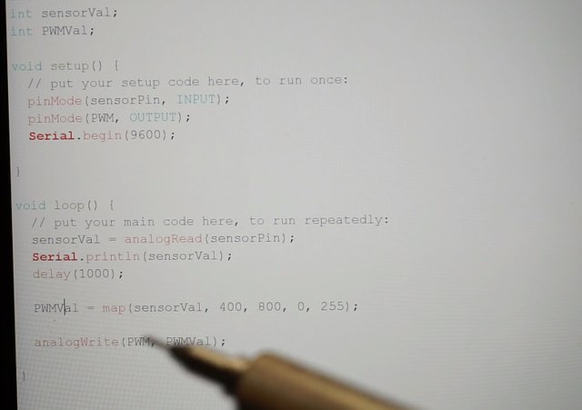
And that's going to be anywhere from 0 to 255. So what I do, I'm going to use the map function. This is going to be very linear. So this is going to behave very linearly. So I'll explain what that means. PWM val, this is going to be our output value in what I'm doing is a mapping the sensor value. And what this means, I'm going to kind of take our bottom limit of our sensor value. Which I said was 400. So this is going to be equivalent to zero on our output. So this if our sensor value read 400, our pulse width modulation or PWM Bell would be zero. And that would actually write nothing out to the fan, right? And if it went up to as high as 800 or maximum value. So it's going to map that to 255. And it's basically going to try and map this as linear as it can.
So it's going to take this 400 make it are lower value. It's going to output that as a zero and it's going to take our 800, make that our upper value. I'll put that as 255. And that's 100 percent pulse width modulation or pretty much just straight 12 volts. And it's going to take these values and is going to sign them to PWM val. So it's going to be basically looking at our sensor values and mapping them on a range from zero to 255. And out putting that to our PWM bells. And then all I'm doing an analog right down here. and I'm writing our PWM output pin to our fan. That's the actual pin three. And I'm writing it, PWM Val and PWM bells, just that value that we just talked about. So that was the actual value of the pulse and pulse width modulation for the fan.
And so there are some issues with this, for one. The fan takes quite a bit of current when it first kicks on. So you might be pulse with modulating your fan as much as 25 percent and it'll put power into the fan. But the fan might not actually start spinning it. So what I would recommend is, we might add some other code here, which when the fans first kicks on, it runs a fan at 100 percent for say a second. And then it goes down to the pulse width modulation value. Because if you don't do that in the fan, starts off. Let's just say zero and then you start feeding pulse width modulation into it. It might not actually start spinning until you get to 30 slash 40 percent because sometimes those fans take a large amount of current to just start up.
So we'll do that by applying a, let's just say a 100 percent value for some amount of time. And I'll show you guys that in the end I just want to show you this simple code running here on the actual circuit. So let's go ahead and take a look at this.
Okay guys. So here is the setup and it's pretty much ready to go. Everything's good to go. I'm just going to turn on the power supply and so you can kinda hear it. Actually you can hear that ringing noise and that is also for modulation. As you can see, the fan is not spinning yet. You might've seen it tried to turn on. But it's not actually spinning yet and that's because what I just explained it earlier. These fans take quite a bit of power to start up. If we actually gave the fans a little bit of a push, it would at this point it's barely going enough, but sometimes it'll have just enough to actually get itself going.
And that's why when we turn the fan on. I want to add a little bit of code to where when the span first turns on Bull, run it at 100 percent for say a second. And then we'll go into our pulse width modulation also. I don't think it's really worth pulse with modulating these guys probably below 10 percent. Because it's not going to have enough power to actually maintain the fan spins. So we'll probably map it to go from say 10 percent duty cycle up to 100 percent rather than from zero percent to 100 percent. But what we'll start tuning in a little bit. I just want to show the very basic operation. So you can kinda hear it going. And I'm going to take the soldering iron, I'm going to touch the sensor. You can, there it goes, you can hear that frequency, but the pulse width modulation changing, starting to speed up. And it's going to go pretty quick because we're hitting the sensor up quite fast.
And so there is another issue with this. That I didn't really explain, but if we go over our map value. If we hit 100 percent, this is actually going to go. If we go past 100 percent. So what if we go over 800 on this sensor?
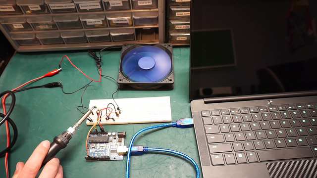
Essentially our map is going to start very beginning and it's going to zero percent again. So you'll see that here. It's slowing down our sensors actually above a 100 right now. It's going to cool off and it's going to kick in again. It's going to come in at 100 percent right there. So that is a flaw with our code. So I'm going to rewrite the code and I'll show you guys a little bit of an updated version with some. Some of these problems worked out.
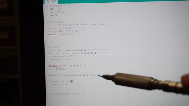
Alright guys, so I just want to show you a few of the fixes I made to those problems and I post this code.
int sensorPin = A0;
int PWM = 3;
int sensorVal;
int PWMVal;

   void setup() {
     // put your setup code here, to run once:
     pinMode(sensorPin, INPUT);
   pinMode(PWM, OUTPUT);
   Serial.begin(9600);

 }

  void loop() {
  // put your main code here, to run repeatedly:
  //this code prints sensor value to the console
  Serial.println(sensorVal);
   delay(1000);

   //read sensor value and set upper limit cap
 sensorVal = analogRead(sensorPin);
 if(sensorVal >800){
   sensorVal = 800;
  }

  //map and assign pwm values to the fan output 0 to 255 corresponds to 0 to 100%
  PWMVal = map(sensorVal, 450, 800, 26, 255);

 //set 450 as out cutout or cut in limit where the fan switches from off to the lower PWM limit
    if(sensorVal <450){
      PWMVal = 0;
  }

    //write the PWM value to the pwm output pin
   analogWrite(PWM, PWMVal);

}
Again, you can tweak these values to meet. whatever really kind of criteria you need for your project. or however you want the fan to behave. You can get really advanced with this as advanced as you want. But this is just very basic. So let's take a look at it.
So before we had the problem with our value, if it went over 800. It would basically loop around again and we'd start at our lower value of our duty cycle. So I kept that off. So basically here's what's going on. We're reading the sensor value and I'm saying if the sensor values greater than 800. Let's go ahead and bump it back down to 800.
So that's going to say the the sense of volume will never retire. Then 800. If it does, we're just going to push it back down to 800. Anyways, this is our older, a stereo monitor code. We don't really need this for the CCO, for the actual program to operate anymore. It doesn't really matter. But I'll just leave it there. The actual PWM values, this is mapping function that we did before. So basically I'm going from a range from 450 up to 800 now. So I bumped our range up. And if it's below 450, if our actual sensor value is below 450. I'm going to actually make our PWM value zero. So this turns the fan off. So it's in an off state and basically once we hit 450, I want to start the fan at a 10 percent duty cycle.
That's what 26 is. It's about a 10 percent duty cycle. That way fan has enough power to actually turn on and it goes pretty slow at 10 percent. So that's good enough. And 800 is still our top range, and that's going to 255 or 100 percent duty cycle.
So this map function works perfect now and it won't actually overflow and a loop around again. So that's what these limits do. And if we're below for 50, like I said, we just turn the fan off, the PWM zero, which rates at zero percent duty cycle to the fan. And in the very end we still have our analog right where we write the PWM value to the actual PWM pin for our fan. So let's go ahead and take a look at this new code and operation.
FUNCTION
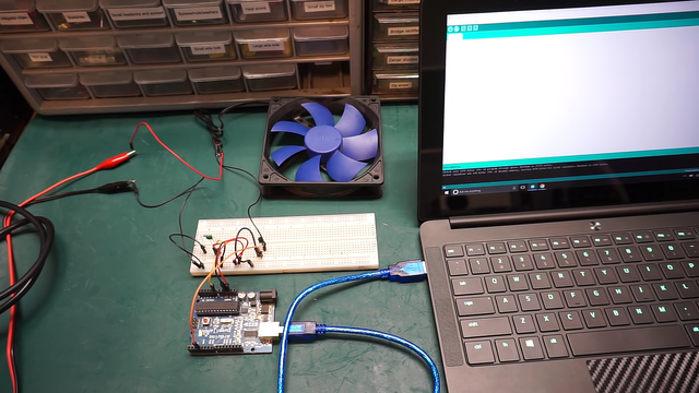
All right guys. So let's go ahead and see this code and operation. It's on now the power supplies on and our sensor value is below that 450. Both thresholds are fantasy is currently off. And uh, if I take the soldering iron called touch it a little bit and you'll see it kicks in at that 10 percent duty cycle, which is enough to actually start the fan.
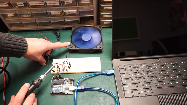
Just go ahead and do that kicks in right there. I barely enough to start the fan. So we might have to start at a higher percent duty cycle. And it starts to ramp up there. You can hear it speeding up, still going. You can hear that ring and there it goes so you cannot hear the ringing anymore. So that's means it's not really pulse with modulating instead of 100 percent duty cycle. So the fan is all the way on or herds had 100 percent duty cycle. So that is the upper limit. That's the 800 or higher limit on our sensor. And so as I take the iron off it will start to cool off and we'll watch it kind of slow down. This is in real time so it might take a minute, you can hear it. There comes a PWM and if I put my finger on it I'll absorb some of the heat off the sensor. It'll slow down a little bit faster.
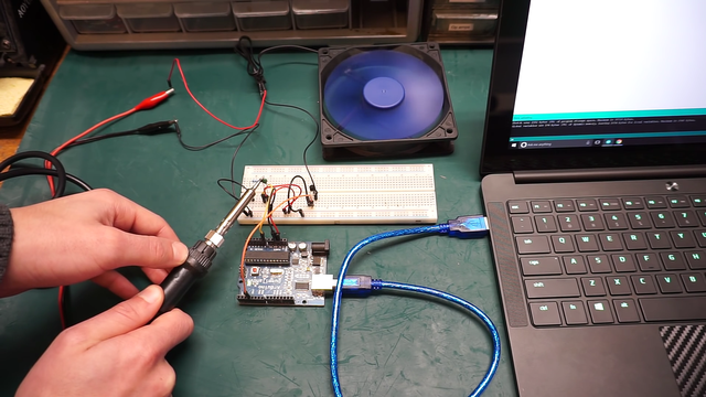
Now we'll just let it cool off from the ambient air temperature and you can see it starting to slow. I don't know if you guys can see that really well in the tutorial, but it is slowing down quite significantly.
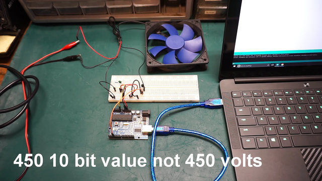
I could actually use the fan to cool the sensor off and so it's really come into a good slow.
Now there it goes and we're gonna hit that 450 limit, the 450 value limit of our threshold. Where the fan will actually kick out and turn off. So it's really slow now. So you might really not want to start out at 10 percent. You might want to start out at say 25 percent. But there it is. So there's that limit where it kicks off. Alright, that pretty much wraps it up for this one.
That code for you guys to look at it and you guys can kind of modify it to meet your own needs. However you guys need it. It'll depend on really what kind of a fan you're working with, and what your project really needs. But you can get as wild and crazy with that as you want.
It doesn't really matter.
So I hope you guys enjoyed this tutorial.
.jpeg)
.jpeg)
The contents, code, screenshots of this post are taken from this youtube video:
Join our Discord Channel to connect with us and nominate your own or somebody else's posts in our review channel.
Help us to reward you for making it ! Join our voting trail or delegate steem power to the community account.
Your post is also presented on the community website www.steemmakers.com where you can find other selected content.
If you like our work, please consider upvoting this comment to support the growth of our community. Thank you.
Your support has been removed. Plagiarism of https://www.youtube.com/channel/UChdftwUR90NbYacO-kcvXyg
We are so fortunate to have an innovator like you on steemit.
Did you know?
Morphine is named after 'Morpheus', the Greek god of dreams.
Read on and follow @knowledge-portal to find more latest discoveries and interesting related facts on the blog.
Congratulations! Your post has been selected as a daily Steemit truffle! It is listed on rank 5 of all contributions awarded today. You can find the TOP DAILY TRUFFLE PICKS HERE.
I upvoted your contribution because to my mind your post is at least 33 SBD worth and should receive 317 votes. It's now up to the lovely Steemit community to make this come true.
I am
TrufflePig, an Artificial Intelligence Bot that helps minnows and content curators using Machine Learning. If you are curious how I select content, you can find an explanation here!Have a nice day and sincerely yours,

TrufflePigCongratulations! This post has been upvoted from the communal account, @minnowsupport, by bramvbilsen from the Minnow Support Project. It's a witness project run by aggroed, ausbitbank, teamsteem, theprophet0, someguy123, neoxian, followbtcnews, and netuoso. The goal is to help Steemit grow by supporting Minnows. Please find us at the Peace, Abundance, and Liberty Network (PALnet) Discord Channel. It's a completely public and open space to all members of the Steemit community who voluntarily choose to be there.
If you would like to delegate to the Minnow Support Project you can do so by clicking on the following links: 50SP, 100SP, 250SP, 500SP, 1000SP, 5000SP.
Be sure to leave at least 50SP undelegated on your account.