CARS; MANUAL TRANSMISSION (CLUTCH)
INTRODUCTION
Basically car are either manual transmission or an automatic transmission, the term transmission in automobile implies the processes or configuration that enable the transfer of power or torque from the engine to the traction of the tyres for different speed and to drive other neccessary motion. Here the manual transmission would be discuss, the term manual simply means that an individual will play a major role in the transmission process. Manual transmission were the first type of transmission system that were made during the first generation of cars. It working principle and major parts would be discussed.
MAJOR PARTS OF A MANUAL TRANSMISSION SYSTEM
▪The gear box
▪The clutch system
▪The gear selector
●THE GEAR BOX: To understand the principle of a gear box, one should understand the working principle of a gear and why the gear is introduce to the system. Gear works using a mathematical model of gear ratio, where the speed of a gear is inversly proportional to it own number of teeth
[N1/N2=T2/T1]
N = Speed of gear
T = Number of teeth
There are various configuration of gears in the gear box but the simpliest common configuration would be explained.
The gear box consist of 3 shaft of which different gear is connected to the different shaft. This shaft include:
•Input shaft
•Output shaft
•Counter shaft
A shaft is simply a circular sectioned rod using in transmitting power or torque.
The input shaft which have a single gear(the green gear for the gif) transmits the torque or power from the engine into the gearbox where the speed can be varied and also its direction can be alternated(reverse).
The output shaft (the blue shaft in the gif) which have multiple gear connected to it depending on the number of speed configuration of the designer, in most cases it is made up of 5 speed motion gears and 1 reverse speed. The speed increases for gear 1 to gear 5.
The counter shaft(the red shaft in the gif) which have 6 gear which meshes the input and output shaft gears in the 5 speed gear, generally the gears in the counter shaft are known as the counter gears.
Their working principle
As said earlier, the gear speed is inversely proportional to it number gear teeth it means that small gears which have lesser teeth will have greater speed. So as the input shaft transmits power into the gear box, the counter shaft recieved it via gear meshes, hence depending on the gear which was selected using the gear shift mechanism which is usually a synchronizer, the gears size in the counter shaft is increasing with respect to the number of speed meanwhile the gear size in the output shaft is decreasing with respect to number of speed.
As the gear is already meshed together with respect to their numbers and all gears in the output shaft are free to roll about the shaft except on the occasion when the gear shift mechanism pushes the synchronizer(which is fixed to the output shaft) to the gear selected and the gear selected meshes with the synchronizer and the output shaft move at the particular speed selected which is the speed of the gear. This is done for all five speed and the reverse gear uses a fourth gear called the idle gear which changes the direction of the rotation due to its odd number of total working gear.
It is a very difficult task to shift the synchronizer while the gear are rotating which will cause a the destruction of the gear teeth, so one will have to switch of the engine before gear can be change. switching off the engine and switching on is a wasted of time, this process have been eliminated by the inclusion of the clutch system
●THE CLUTCH SYSTEM: A clutch system is simply a mechanism that causes discontinuity in the flow of power between the engine and the gear box. It works with the principle of FRICTION and SPRING FORCES.
PARTS OF A CLUTCH
▪The Clutch Disc
▪The Pressure Plate
▪The Release Bearing
The Working Principle
Consider two slightly rough surfaces which are in contact with each other, hence both having a single degree of freedom which are the same, they will both move together if an external force is acted on them and when they are not in contact, the will act indepently to each other with respect to their motion.
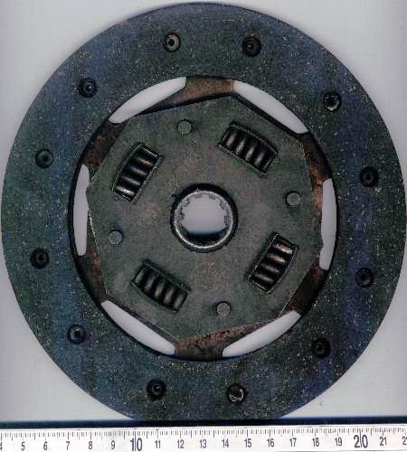
THE CLUTCH DISC
the inclusion of springs is to absorb or rather dampen the speed fluation in the engine.
The clutch system simply works in this manner, a flywheel which is connected to the crank shaft which is slightly rough and rotates at the same speed as the engine, And also a clutch disc which is fibrous in nature is in contact with the flywheel, they both rotate at the same speed if they are in contact with each other and the output shaft in the gear box is connected to the clutch disc via a teeth mesh hence a force is acted on the disc to keep a firm contact.
This force that keeps the clutch disc and flywheel in firm contact is provided by the pressure plate, the pressure plate is simply a slightly rough surface that is incorporated with springs at its behind to provide a thrust force to the clutch disc. It is also made up of a Diaphragm spring , the diaphragm principle is a push action and pull reaction.
When the diaphragm spring in the pressure plate is pushed mean while the engine is still running, the forces exerted by the pressure plate is withdrawn, hence causing the clutch disc and the flywheel to loose contact, this causes a discontinuity between the engine and the gearbox. the push is done via the release bearing.
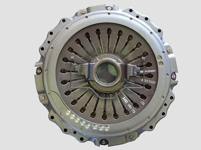
PULL TYPE CLUTCH PRESSURE PLATE WITH A RELEASE BEARING
.jpg)
A CLUTCH DISC, PRESSURE PLATE AND FLYWHEEL ASSEMBLE
.jpg#mw-jump-to-license)
Another mechanisms that would be explained here is how the release bearing is operated inside the engine. this is done either by a mechanical means which is a pedal and cable means or more efficient way which is the hydraulic means.
The hydraulic method simply works with the pascal principle of pressure
a pressure change occurring anywhere in a confined incompressible fluid is transmitted throughout the fluid such that the same change occurs everywhere.
consider two cylinder sleeves which is incorporated with a piston in it and are connected in such a way that a tiny tube controls a fluid flow from one cylinder to the other and both cylinders are filled with an incompressible fluid, If the piston in one cylinder is moved in such a way that it tends to reduce the volume of the fluid in that cylinder, a corresponding increment of volume in the other cylinder is observed, from pascal principle it can be deduced that the force exerted on one piston is equal to that of the other piston, provided that the area of the cylinders are equal and the fluid is incompressible, these forces can be magnified by alternating the cylinder area.
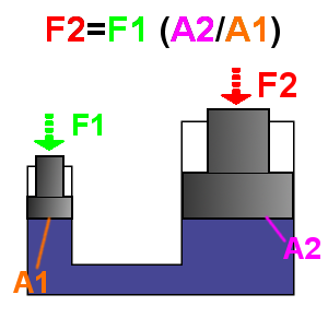
PASCAL PRINCIPLE OF INCOMPRESSIBLE FLUID FLOW
so therefore from the above explanation, the force recieved from the second piston is what pushes the release bearing and then the clutch is disengaged, this happens when the clutch pedal of a car is stepped on.
The cylinder sleeve in the pedal of the car is known as the Master clutch cylinder and the cylinder sleeve which recieves the fluid located at the gearbox is know as the peripheral cylinder or the down clutch.
REFERENCE
▪Basic knowledge gained from UNIVERSITY OF BENIN ENGINEERING WORKSHOP, NIGERIA
▪Basic knowledge gained from PETER MARTINS AUTOSHOP, BENIN CITY NIGERIA
▪

Source: Designed by @hboi
With the major objective of steemSTEM to advance Science, Technology, Engineering and Mathematics on the Steem blockchain. In the event that you wish to help the steemSTEM to promote their major objectives, which can be done by contributing on STEM content and using the tag #steemstem , also support steemstem creators ,join the curation trail and you can also delegate SP to steemstem.
I used my upvote on this post 👍 and am following you because I too love anything mechanical and see the world as parts and simple machines without even trying. It’s good to see posts like this (even though it’s not new info to people that are mechanically inclined) I like to meet others that take the time to explain in detail things most people don’t ever wonder about.
Congratulations @engr.martins! You received a personal award!
Click here to view your Board of Honor
Do not miss the last post from @steemitboard:
If you need more then transmission manual check this https://carmanuals7.com/
Congratulations @engr.martins! You received a personal award!
You can view your badges on your Steem Board and compare to others on the Steem Ranking
Vote for @Steemitboard as a witness to get one more award and increased upvotes!
Resteemed your article. This article was resteemed because you are part of the New Steemians project. You can learn more about it here: https://steemit.com/introduceyourself/@gaman/new-steemians-project-launch