Digital Electronics Series - Basics of Logic Gates
Building Devices with Logic Gates – Part 1
We all use various forms of computers in our daily lives. These computers contain various units such as the central processing unit and the arithmetic and logic unit.
At the heart of computer electronics, there are electronic components called logic gates, which control and transfer the flow of current. When used together, arrays of logic gates can achieve lots of useful functions such as mathematical operations such as addition, subtraction or multiplication.
Read on, so the next time you ask your computer what’s 1 + 1, you can really appreciate how the answer is calculated by using electronic components.
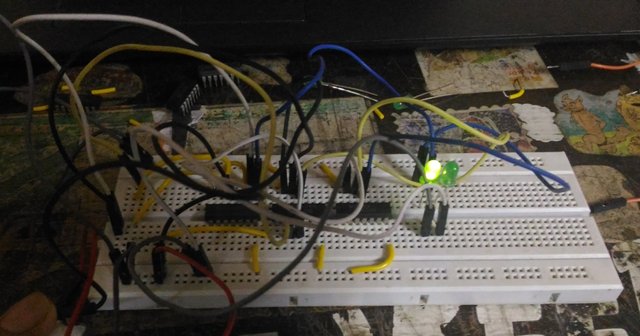
(I gave two inputs 01 and 01, i.e 1 + 1, The output is, as you can see with the LEDs lighted up, 10. Now 10 in binary is 2. The logic gates used together just added the two inputs and outputted their sum! How cool is that!)
Here, I tried to make a simple calculator using only logic gates. This is a Full Adder circuit, which takes two binary numbers as its input and displays the sum, in binary format. Binary format is very simple to learn and we will discuss it later.
Logic Gates – The Basics
Logic gates are the most basic building blocks of digital electronics. They have inputs and outputs and the outputs are related to the inputs by a certain logic, which depends on the type of logic gate you are using. This will be discussed later when we look into the different types of logic gates.
The inputs of a logic gate can only have two values. It is either a 1 or a 0. Here, 1 is a high voltage and 0 is a low voltage. So 1 can mean 5 volts and 0, well, ground, or 0 volts. The neatness in using 1s and 0s is that you can represent numbers easily with 1s and 0s. Yes, I’m talking about the binary system of numbers.
A binary number, at the most basic level, represents decimal numbers as sums of powers of two.
We know that
5 = 4 + 1
ie, 5 = 1 x 22 + 0 x 21 + 1 x 20
Therefore binary for 5 would be 101
In a binary number, the left mot digit represents 20, the 2nd digit from left 21 and so on. A 1 at the position of 20 indicates that there is a term of “1”(20) in the number. A 0 at the 2nd position says that there is no 2(21) and a 1 at the third digit indicates a 22 , that is 4. So the decimal number is the sum of all these numbers. That is , 4 + 0 + 1 = 5.
Neat isn’t it?
Now we can study the different types of logic gates.
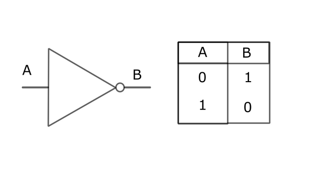
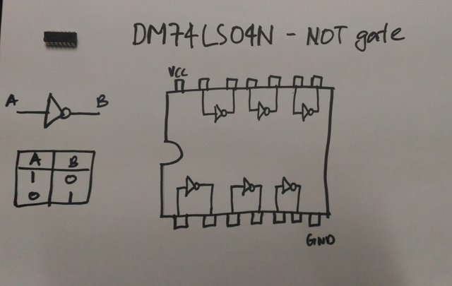
1.The NOT gate or the Inverter
This might be the simplest of the gates. It has only one input. As the name suggests, its an inverter. It inverts. If you give a 5v input, the output will be 0v. If you don’t give any input signal, you’ll get a 5v signal. Give a 1 and you get a 0, and vice versa.
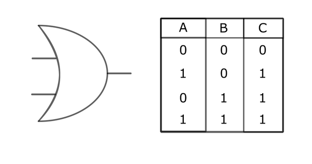
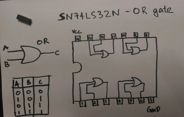
2.OR gate
It has got n inputs and one output. As the name suggests, the output will be a 1 if any of the inputs are a 1. The output will be 0 only when all the inputs are 0.
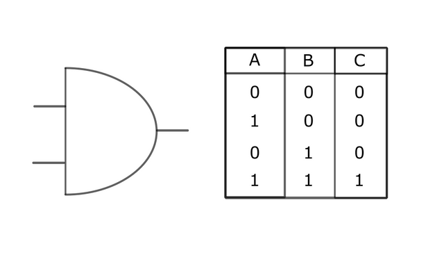
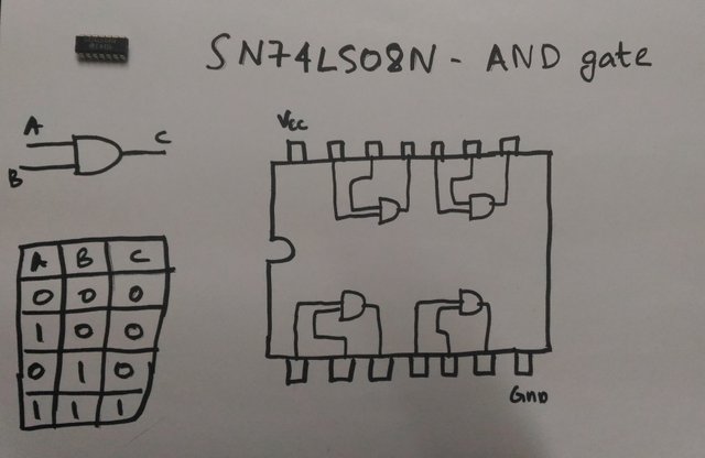
3.AND gate
It has n inputs and an output. The output will be a 1 only when all the inputs are 1. In all the other cases, the output will be 0.
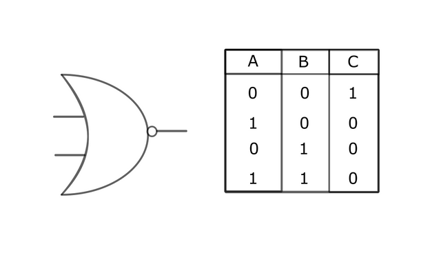
4.NOR gate
It is very similar to the OR gate, the only difference being, the output will be inverted. A NOR gate is equivalent to placing a NOT gate at the output of an OR gate. The output will be 1 only when all the inputs are 0. In all the other cases, the output will be 0.
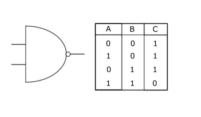
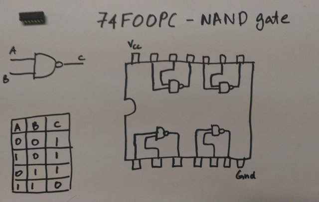
5.NAND gate
The NAND gate is to the AND gate, what NOR is to OR. NAND is just an inverted AND gate. The output of the AND gate, taken through a NOT gate.
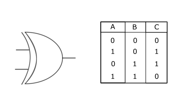
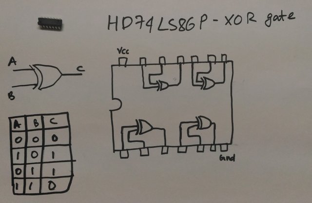
6.Exclusive OR gate (XOR)
It is based on the OR gate. It is a logic gate with two inputs and an output. If any of the inputs (but not both), is 1, the output is 1. The output will be zero when both the inputs are 0 or 1.
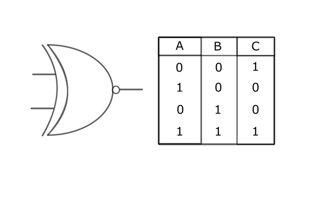
7.Exclusive NOR gate (XNOR)
It is based on the NOR gate. It has two inputs and an output. When both the inputs are either 0 or 1, the output is 1. When one of the inputs is 1 and the other 0, the output is 0.
Now that we have learned about all the basic logic gates, let us further learn about how we can use these basic building blocks to build useful logic circuits that can do calculations and stuff for us.
But after seeing all this you might wonder, “But what exactly are these ‘gates’?”
It’s a good question and I have wondered about it too.
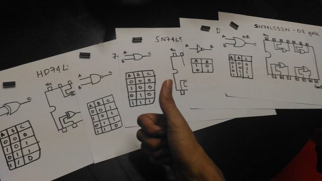
Logic gates are special circuits that are designed to realise the condition that we mentioned above while describing them. They are available in the form of integrated circuits, with multiple gates embedded onto them.
For example, take a look at these : -
Independently, any logic gate can be made from transistors. I’ll talk about this in an entirely different article. It is the same configuration of transistors that are used while designing and fabricating the ICs. In fact, you can create each and every logic gate by yourself using only transistors. It can be fun to experiment and learn, but for all the projects that we do in digital electronics, we will be using the gates available in chips only. They are much compact and are easier to use and debug in our circuits.
That’s the end of first part of the Digital Electronics series! Tell me what you think about this and stay tuned for the upcoming articles!
Image Source
All the images shown are made/taken by me.
Proof of work :-
My lady got me a raspberry pi for Christmas, and I've been aiming to get int the hardware aspect of this. Very informative post! Will be keeping an eye out for you in the future :)
good work there, keep it up
I remember this back then in school, it was alway an interesting class and way the lectural explain the gates are cool.
Congratulations @filler! You have completed the following achievement on Steemit and have been rewarded with new badge(s) :
Click on the badge to view your Board of Honor.
If you no longer want to receive notifications, reply to this comment with the word
STOPTo support your work, I also upvoted your post!
Do not miss the last post from @steemitboard:
SteemitBoard World Cup Contest - Russia vs Croatia
Participate in the SteemitBoard World Cup Contest!
Collect World Cup badges and win free SBD
Support the Gold Sponsors of the contest: @good-karma and @lukestokes
Great post...but i didnt know much on that. Keep it up, anyway!
Join our Discord Channel to connect with us and nominate your own or somebody else's posts in our review channel.
Help us to reward you for making it ! Join our voting trail or delegate steem power to the community account.
Your post is also presented on the community website www.steemmakers.com where you can find other selected content.
If you like our work, please consider upvoting this comment to support the growth of our community. Thank you.