Smith Chart Made Life Easy : Matching Of Impedances
From previous article, i have dealt on transmission lines. In this article we are going to learn about the most important application of Transmission Lines, which is “Impedance Matching”.
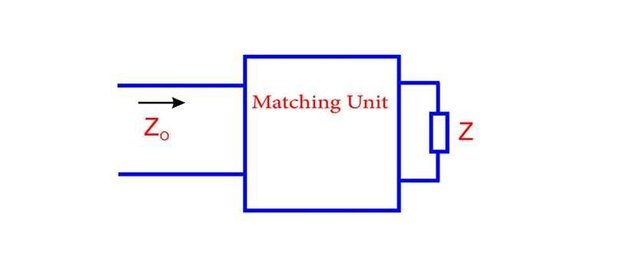
When impedance is equal to characteristic impedance (Zo), there is no reflection on the line, hence there is maximum power transfer. But as we have seen, this matching condition is not always feasible. We then need a module or device which will transform this impedance to the characteristic impedance. This module is known as a matching unit or matching transformer.
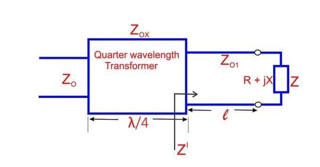
Let’s start with the first example which has a matching unit (transformer) which can convert the output (Z) impedance to the characteristic impedance Zo, which is shown in figure 1.1. At the input (left most side), we should see a characteristic impedance Zo and the module should be completely lossless (ideal) to allow maximum power transfer to load(Z).
Let’s discuss various method by which different impedances can be matched to the characteristic impedance.
In figure 1.2a we have two different resistance R1 and R2
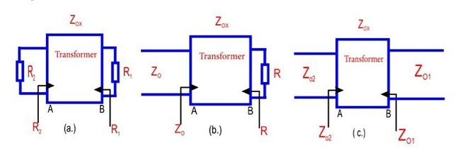
which are to be matched, i.e R1 not equal R2. If they are connected directly there will be a mismatch and no maximum power transfer from R1 to R2. We then introduce some device in between that will make R1 appear like R2 when seen from left side and R2 to appear like R1, when seen from the right side, so from both side it will appear that they are matched to the load and there is maximum power transfer.
In figure 1.2b, we are matching R to Zo, so we place in a module which help us to match the impedances between R and Zo. Hence at the left side we should see Zo. Also in figure 1.2c, which is the most important case. We have two(2) long transmission lines which are to be connected together. If the length of each transmission is very large, the input impedance of transmission line one(1) will appear as its characteristics impedance (Zo1 ) and transmission line two(2) will appear as its characteristics impedance Zo2 . Making a straight connection between them, Zo2 sees itself connected to Zo1 and vice-versa. This will cause an impedance mismatch and reflection towards both side at the junction of transmission line. So we bring a transforming device in between that will make Zo1 see Zo2 as Zo1 and vice-versa. From both sides, it seems as if the line is terminated in its characteristic impedance. Hence there will be no reflection on either side of the transmission line.
Quarter Wavelength Transformer Technique
On the smith chart, if we have an impedance which is resistive, how much can we move on the transmission line so that the impedance always appear like a resistance? Let us introduce some section of transmission line in between both impedances (input and output) which have a characteristic impedance Zox in figure 1.2a and 1.2b and is different from the characteristic impedance Zo to which the resistive impedance R is to be matched.
Hence, we find out Zox and the length of this introduced transmission line for which R can be matched with Zo . Resistive impedance lie on the horizontal axis of the smith chart, Z > Zo lies on the right and Z < Zo lies on the left of smith chart. So the question is: What should be the value of Zox and length L, that will match the resistive impedance to the characteristic impedance( Zo )? From the smith chart shown in figure 1.3, to see a resistance again, we move λ/4 or λ/2. λ/2 movement
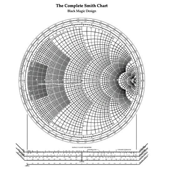
brings us back to the same impedance. We won’t use this value because it will transform the impedance to itself. λ/4 movement will have a resistive impedance which is different from the original resistive impedance(i.e inverts itself). L= λ/4 will be most appropriate because at this length we will have a different resistive value.
From figure 1.4, at the transformer (output), the normalize impedance seen will be R/Zox . At the transformer(input), the normalize impedance seen will be Zox /R (we know from property of transmission line, that every distance of L = λ/4, the impedance inverts itself). So the absolute characteristic
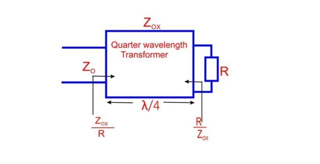
impedance(Zo) seen at the input will be equal to:

What does this tell us? This equation tells us that if we have a mismatch condition, we can input a matching transformer ( an example is the BALUN). Introducing this section of transmission line, we will have a matched condition where R will appear as Zo when seen from the input and Zo will appear as R when seen from output. Since line is lossless, there is a match on the
transmission line from Zo to R, therefore, we will see a maximum power transfer. This technique of matching impedance is known as the Quarter Wavelength Transformer Technique which derives its name from the fact that we have to travel a length which is equal to a quarter, i.e 1/4 of the wavelength(λ). This matching transformer is also used for matching lumped circuit.
Complex load impedance
A question may be asked: if this technique(quarter wavelength transformer technique) is only used to match resistive impedance? The answer is absolutely No! We can use this method to solve complex impedances but it requires us to do some thinking because on the first look, it appears impossible. This is because on the smith chart shown in figure 1.3, to derive Zox, we use only the horizontal axis of the chart. Now, how can we use both the real and imaginary parts of the chart?
As we saw earlier, we need to do some proper thinking to solve complex load(Z). We solve it by first transforming the complex normalized impedances to a real impedance by moving along the length of a transmission line. That means if you introduce some length of transmission line with characteristic impedance (Zo), then the impedance seen at the other end is real if the length is such that you get a voltage (maximum or minimum) for that length.
From figure 1.5, we have to move Z which is complex by a distance L on the transmission line to make its transformed impedance real at point B.
Using analytical method may be time consuming and tedious, so we use a smith chart to solve the problem.
Procedures:
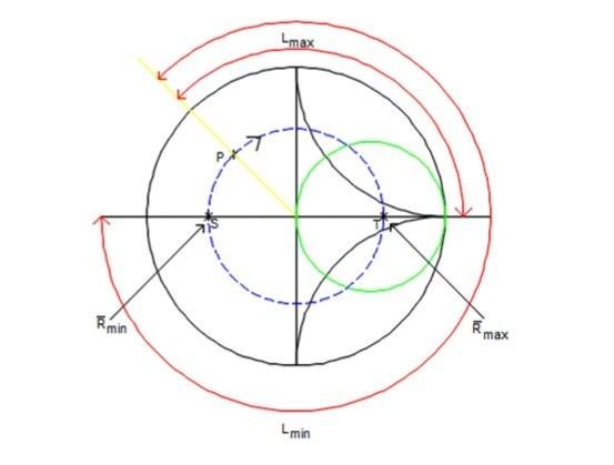
1• Let Z = R+jX normalized become point P = r+jx** on the smith chart shown in figure 1.6.
2• From point P, draw a constant VSWR circle.
3• As we move on a constant VSWR circle (clockwise), we reach a point T which is a real impedance Rmax. As we movefurther, we reach a point S which is also a real impedance Rmin.
4• Lmax represents the distance from point P to T, while lmin represents the distance from point P to S.
5• If we know the VSWR (ρ), the normalized impedance at point T and S would be known.
6• considering distance lmax, the absolute impedance
at point T is
7• considering distance lmin, the absolute impedance (Z') seen at point S is
8• Therefore the absolute impedance (Z') at point B in figure 1.5 can be found using either Rmax or Rmin.
Therefore the characteristics impedance of the quarter wavelength transformer Zox would be:
OR
Any solution is acceptable depending on whether we want the length L, to be small or large. If we are taking cost into consideration, we will choose for shorter length of the transmission line.
Conclusion
In conclusion, we can say that Quarter Wavelength Transformer technique can be used for matching complex impedance (Z) to real impedance(Zo). However, it has a big drawback in that you require a unique characteristic impedance Zox for the transforming device for different load Z. This is not desirable and realizable in nature because in practice, we do not get a Transmission Line whose characteristic impedance can be varied easily. The characteristic impedance Zox depends on the physical dimensions of the transmission line. We have cables of transmission line with standard characteristic impedance. For example for co-axial cable, the characteristic impedances are 50Ω and 75Ω. For parallel wire transmission line, the characteristic impedances are 300Ω and 600Ω.
NOTE: ALL IMAGES ARE ORIGINAL
1• Floyd, Thomas (1997), Principles of Electric Circuits (5th ed.), Prentice Hall
2• Hayt, William (1989), Engineering Electromagnetics (5th ed.), McGraw-Hill
3• Karakash, John J. (1950), Transmission Lines and Filter Networks (1st ed.), Macmillan
4• Kraus, John D. (1984), Electromagnetics (3rd ed.), McGraw-Hill
5• Sadiku, Matthew N. O. (1989), Elements of Electromagnetics (1st ed.), Saunders College Publishing
6• Young, E. C. (1988), "maximum power theorem", The Penguin Dictionary of Electronics, Penguin
7• Young, E. C. (1988), "impedance matching", The Penguin Dictionary of Electronics, Penguin
8• Lecture note

With the major objective of steemSTEM to advance Science, Technology, Engineering and Mathematics on the Steem blockchain. In the event that you wish to help the steemSTEM to promote their major objectives, which can be done by contributing on STEM content and using the tag #steemstem , also support steemstem creators ,join the curation trail and you can also delegate SP to steemstem.
This is a nicely researched and written electrical engineering post, I don't see as many on Steemit. You did a fantastic job.
Can I steal your gif at the end?
Thanks a lot, you are free to make use of it.
Thank you.