A Beginner's Guide To The Multimeter: Troubleshooting With The Multimeter
In my previous articles, I have explained explicitly the working principle of the multimeter and have elaborated the pros and cons of the digital multimeter as well as its analogue counterpart. It is imperative to go through the previous episodes of multimeter guide so as to understand fully, the troubleshooting feature of multimeter and even use it in troubleshooting. The summary of the previous series is as summarized below
The operating principle of a multimeter is based on mainly three main general principles which are Hooke's law of elasticity, the force on a current carrying conductor and the magnetic field crated on a current carrying conductor. The higher the magnitude of current being measured with the multimeter, the more the deflection of the needle of the multimeter. The needle is pivoted on a mechanism that can create magnetic field. You can click operation principle of multimeter to learn more on this
Introduction
Just like a doctor cannot do without a thermometer, a programmer cannot code without a computer, a driver cannot drive without sterling, so also an Engineer cannot work without a meter. It might me ammeter, voltmeters, ohmmeter or a meter that integrates all the aforementioned meters in one meter rather called a multimeter. Acquisition of multimeter is the beginning g of electrical or electronics Engineering, hence we can say that multimeter is the most romantic property and electrical or electronic engineer should acquireTroubleshooting of electronics and electrical equipment is the most important function embedded in multimeters. With a multimeter, you can test for fault or failure of any component in an electrical or electronics system. If you have being to any electronic repairer's workshop, you would have seen that the Engineer would not tell you the fault of any system till he runs some test with his multimeter ( although some engineers can tell you a fault based on their experience or encounter with similar fault)
Anybody that calls himself an Electrical Engineer or even intends to become an electrical Engineer without knowing how to troubleshoot with the multimeter can be likened to an English language teacher who does not know how to read A-Z or even a driver who does not know how to match the break pedal of a vehicle. However, you do not have to worry if you fall in such category because this post will enlighten you and widen your intellectual horizon with respect to the troubleshooting feature of multimeter.
Troubleshooting
Troubleshooting which is the detection of fault or test for fault in an electrical/electronics system can be done using the multimeter. And depending on the fault you what to check on, there are options on the multimeter to select from; this can be done by simply turning the knob of the multimeter to the required position. This means that troubleshooting for faulty resistor and faulty AC extension should take different position on the multimeter.For all the troubleshooting, plugin the black probe wire to the negative(COM) channel of the multimeter and the red probe wire to the positive(VΩ) channel. Before you carry out any test, first turn the knob to the "continuity mode" position and bridge the two probe wires. This should produce a sound if the probe wires are firmly and rightly connected to the "COM" and "V" channel.
Am using Sanwa model DT 9205A digital multimeter for all the troubleshoots here and I have attached a paper masking tap as an indicator or pointer of the direction of the knob
Troubleshooting a Fuse
Troubleshooting a fuse is the easiest fault finding any one that is technical inclined can do with the multimeter. A fuse is generally a string of wire(element) enclosed in a ceramics of glass with two metallic terminals.fault in a fuse is simply a cut in the element used in the fuse, this cut is caused by excess current or over voltage which generates heat above what the element can bear. Hence, a cut.So when you suspect a fuse is faulty, at times cut in the element of the fuse are not easily seen. you have to troubleshoot using your multimeter
To test if your fuse is faulty follow the steps below:
- Turn the knob of our multimeter to the ohm section on the multimeter.
- Connect the two probe wires(red and black) to the two metallic terminals of the fuse.
- Depending on the type of meter you are using, if it is analogue meter, there would be a deflection of the needle if the fuse is still in good condition; if it is a digital multimeter, the 1 displayed on its screen will change from 1 to any random value.
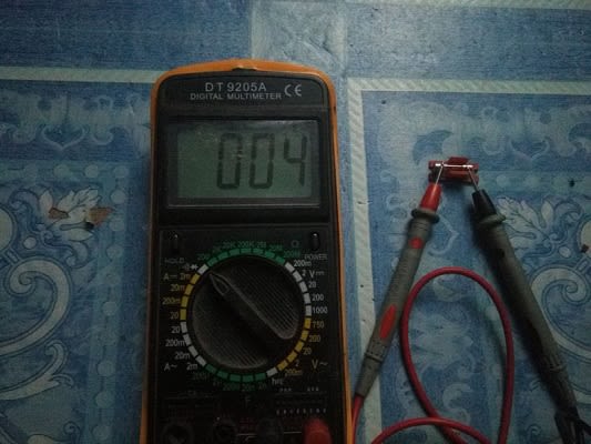
image credit:@ikchris
For easy sake, just turn the knob of the multimeter to the continuity mode position (with the buzz symbol) if the fuse is still in good condition, you would hear a buzz sound; otherwise, the fuse is in a bad state and needs to be changed
Troubleshooting a Light Switch
it is easier to troubleshoot when you know the function of the device you are carrying out a test on. The function of electrical light switch is to complete a circuit(bring in contact two or more conductors in order to achieve a predetermined function). When you turn on you switch control for an electric lamp, that lamp lights because the circuited is just completed, hence current found a path to the lamp.How do you now know if the switch is still good or not?
If the switch is bad that means, it cannot close the path of the electric circuit, can no longer bring in contact, different two or more conductors connected to it. So to test for this using your multimeter:
- Turn your multimeter knob to the continuity section (it has a buzz or zener diode symbol).
- Loose the switch, turn it on
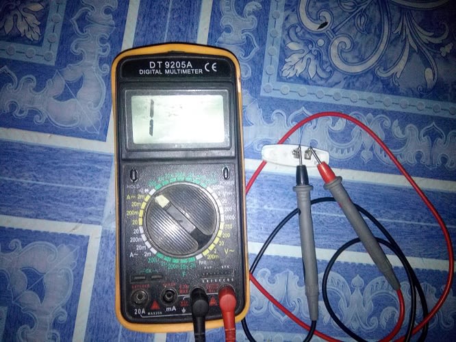
image credit:@ikchris - Connect the two probe wires in the two metallic terminals provided in the switch.
- If the electric switch is still in good condition, you should hear some buzz sound. If otherwise, then the switch is bad, you can simply replace it
Troubleshooting a Resistor
Troubleshoots for resistors are somehow complex in the sense that you have to know resistor colour code or rely on the value written on the resistor case in other to know the appropriate position to turn the knob to.In the multimeter(Sanwa DT 9205A) I have here, there is a provision of <200(buzz symbol), 200, 20K 200K 2M 20M and 200M. So if you are troubleshooting a resistor whose resistance is less than 200:
- Switch to the "continuity mode"
- Connect the probe wires on the two terminals of the resistor,
- You should hear some buzz sound if the resistor is still in good condition.

image credit:@ikchris
However if you a troubleshooting or testing a resistor whose resistance is more than 200 but less than 2K:
- Turn the knob to 200.
- Connect the two probe wires to the two terminals of the resistor,
- The multimeter should display the resistance of that resistor in the screen or show it on the scale, otherwise the resistor is faulty.
To troubleshoot on a resistor whose resistance is above 2K, turn the knob of the meter to 20K an repeat as in above.
Make sure anytime you want to troubleshoot a resistor, you turn the knob to a value more than the resistance of the resistor being tested. Please also try as much as possible to avoid your hand touching the any terminal of the resistor or even the metallic end of the probe wire as this might lead to error in the test due to human body resistance.
Troubleshooting a Diode
The function of a diode is to direct the flow of current in only one path, if something that has two paths to conduct current through only one path, that means one of the paths must be an open circuit while the other is closed.We can liken a closed circuit in the diode as a safety fuse and carry out the test.
So to test if a diode is faulty:
- Turn the knob of your multimeter to the continuity position.
- Place the red probe wire to the positive terminal of the diode(this is usually a circle that envelops the positive end) and place the black probe wire to the other end, you should hear a buzz sound.
- Now, interchange the position of the two probe wires, you should not hear any sound. However, if you hear any sound, that means the diode is in bad condition
Going from anode to cathode of a diode, it would behave like a conductor with negligible resistance; while going from cathode to anode, a diode behaves like a dielectric with infinite resistance. Hence, current cannot from when passed from the cathode but can flow when passed through the anode.
Troubleshooting An LED
Light emitting diode(LED) is a class of diode used as indicator in electronics /electrical equipment and even in mechanical equipment. To test if an LED is in good condition:- Select the continuity part of your multimeter
- Connect the positive probe wire to the positive terminal of the LED and the negative(black) probe wire to the negative terminal of the LED (the positive terminal of the LED is usually longer than the negative terminal.
- If you do this accurately, the LED should give out its predetermined color of light. In case it did not emit light, interchange the position of the probe wires
- If it still do not emit light, then the LED is faulty or in bad condition.
The image of this process is attached below
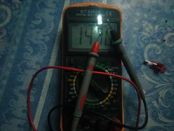
image credit: @ikchris
Troubleshooting a Capacitor
The two main function of a capacitor is to filter out ripple voltage after rectification and to store electrical energy in a circuit, therefore providing the energy when the circuit needs it.Troubleshoot for capacitors is relatively complex compared to the other components we have discussed. There are usually two ways of troubleshooting a capacitors, these two ways depends on the aforementioned functions of the capacitor:
The first one and easier one is:
Turn the knob provided in the multimeter to the "continuity mode" position, the probe wires remains in the "COM" and "V" channels.
Now, listen without distraction while you connect the two probe wires to the two terminals of the capacitor.
You will hear a transient(fading) sound that goes off in milliseconds. Interchange the probe wires, you will also hear a fading sound.
This is so because, as you connect the probe to the capacitor, the battery in the meter charges the capacitor. After the charge, the capacitor discharges, hence an energy is provided for the buzz alarm inside the multimeter.
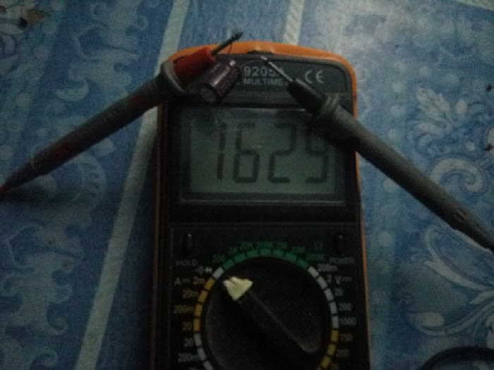
Image credit:@ikchris
The second way to troubleshoot a capacitor, is as below:
- Turn the knob in the meter to the to any of the ohms value the resistance section. The probe wires remains in the initial channels
- Connect the probe wires to the terminals of the capacitors,
- You would see some numbers displayed on the screen(if you are using a digital meter) or a deflection of the needle on the scale( if you are using an analogue meter). For the digital meter, if the numbers goes back to "1" after some seconds, turn the knob to a higher resistance (example from 2K to 200K)
The above test is based on the fact that capacitor filters ripple voltage and also resists some voltage. So the meter displays the magnitude of resistance offered by the capacitor. The higher the capacitance of the capacitor, the higher its resistance to DC which corresponds to a higher value of resistance being displayed on the screen or deflected on the scale.
Troubleshooting an Inductor
An inductor is basically coils of wire. If an inductor has two terminals, then it is only one wire wounded hundred or thousands on a metal; if an inductor has four terminals, it is two separate wires wounded hundreds or thousands on a magnetic base/support structure.The function of an inductor is to eliminate AC while it allows DC to pass, the common fault in an inductor is a cut or cuts(discontinuity) in the conductors used for the coil, this arises due to heat caused by overload, excess voltage or current. Another cause of fault in an inductor is ageing
Just like the capacitor, the inductor can be troubleshooted following the steps below:
- Your probe wires remains in the channel as that of the capacitor and turn the knob to the "continuity" indicated section on the meter
- Connect the two probe wires to the two terminals that have a common turns of wire or coil.
- You will hear a continuous buzz(sound) from the meters. Otherwise, the inductor is bad.
If the conductor has four terminals, repeat the above test for the other two terminals, you would also hear a buzz if that path is still good (there is no cut in the conductor used for the coil)
Currently, I don't have an inductor handy.
Conclusion
Troubleshooting with a multimeter is the most advanced function or feature embedded in a most multimeter and the knowledge of this feature(troubleshooting) is vital for any electrical/electronic engineer or even student engineer.On this basis, we have discussed the troubleshooting of common electrical components. Always bear in mind to turn the knob to "continuity mode", then bridge the two wires to hear a buzz which confirms the probe wire is appropriately connected to the meter channels.
References
- The fucntion of a capacitor
- Overview of electrical resistors
- The function and operation of an inductor
- overview on electrical resistors
- Troubleshooting inductors
- Faults commons in capacitors
- The concept of open circuits and closed circuits
- The fundamentals of electrical switch
- Common faults in a light switch and its troubleshoot
- The fundamentals of diode
- Troubleshooting an LED with the multimeter
- Operating Principle and usage of multimeter
- The element of electrical safety fuse
- Continuity test using the multimeter
Troubleshooting 101. Good one.
I sometimes imagine how some so called electrical engineers work without meter or any other type of measuring device. I was astonished the day I saw a technician hold unto a 50mm cable to check if it is overloaded! My haw nearly dropped to the floor, so he wants to check for a temperature change when all he needs is a current clamp meter to sure of the current flowing through the cable!
The operation of multimeter is a must know for every electrical Engineer . Thanks for coming around
This post has been voted on by the SteemSTEM curation team and voting trail. It is elligible for support from @curie.
If you appreciate the work we are doing, then consider supporting our witness stem.witness. Additional witness support to the curie witness would be appreciated as well.
For additional information please join us on the SteemSTEM discord and to get to know the rest of the community!
Thanks for having added @steemstem as a beneficiary to your post. This granted you a stronger support from SteemSTEM.
Thanks for having used the steemstem.io app. You got a stronger support!
Congratulations @ikchris! You have completed the following achievement on the Steem blockchain and have been rewarded with new badge(s) :
You can view your badges on your Steem Board and compare to others on the Steem Ranking
If you no longer want to receive notifications, reply to this comment with the word
STOPVote for @Steemitboard as a witness to get one more award and increased upvotes!
Moved to the Hive platform.