Once again I can share with you a little more about basic electricity but not before thanking the
@steemstem mentors for the support they have given me by reading my publications and making the necessary corrections to improve. Life is a school where we are learning every day, everything we can learn is a treasure that we must value and thank for. In this issue I want to explain what resistors are used for the design of electrical circuits, their function in circuits and how they relate to each other. Remember to comment on your doubts or suggestions for improvement.
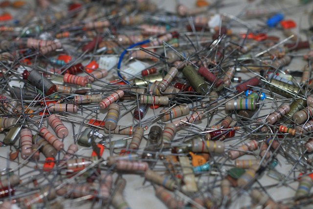
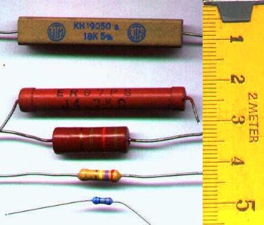
Physical shape of the carbon resistors. Pixabay

Resistors designed to create electric and electronic circuits.
We have already established in previous publications that all materials have an electrical resistance and that the amount of resistance present makes them good conductors of electricity or not. We also defined an electrical resistance as a material capable of opposing or limiting the passage of electrical current through it. Taking advantage of these principles, elements have been created with fixed electrical resistance and some with variable electrical resistances in a certain range (potentiometers) with the aim of designing and developing electrical circuits capable of controlling the current and voltage that reach each element that forms part of it. These elements are called resistors and the material used is generally carbon and ceramic. The unit used to describe resistance quantities is the ohm represented by the symbol Ω
CARBON RESISTORS
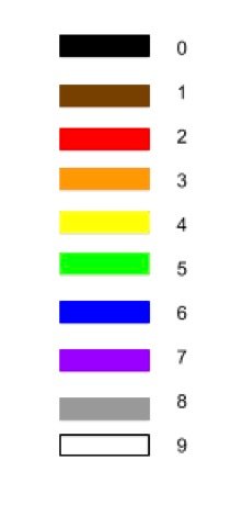
They are manufactured in different physical sizes with power dissipation limits, typically from 1 watt down to 1/8 watt. The values of resistances and tolerances can be determined with the standard color coding of resistances. This code is represented by coloured stripes on the resistors which, according to the colour and the position of the colour, indicate the value of the resistance in ohmns. The first two colors represent two digits that form a quantity, the third color represents a multiplication factor, that is, how many times the quantity formed by the first two digits must be multiplied by 10 to obtain the resistance value, the fourth color represents the tolerance. We can see in the images on the right the numbers corresponding to each color.
CERAMIC RESISTORS
Ceramic is a very common internal component in many different types of resistances. In a carbon film, the resistive material adheres to the outside of the ceramic core, usually in a cylindrical shape. These cores provide a non-conductive base to hold the conductive components in place, and give the strength its size and shape.
Many resistors instead of using color coding simply have their value written down in a very clear way.
Schematic representation and relation of resistances in a circuit
To represent electronic circuits drawing the physical components as they are would be very tedious and would take a long time, for this reason symbologies have been standardized for the elements that form part of a circuit, in this way the design and analysis of them is facilitated, in this sense for the design and analysis of circuits we will use the following symbol to represent resistances  or
or  According to the norm used we will find it both ways in the circuit diagrams, we will also use both symbols in the future when we do simulations, depending on the simulator we use.
ASSOCIATION OF RESISTORS IN SERIES
The resistors have two ends which we call terminals, it is said that two or more resistors are in series when they are physically connected by one of their ends as indicated in the figure on the right, in this case the total resistance obtained will be the sum of all of them RT = R1 + R2 + R3 +...+ Rn , all the resistors grouped in series will be crossed by the same current, but the voltage in each of them will depend on its value in ohmns.
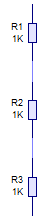
Grouping of resistors in series, image created by the author with the livewire simulator
ASSOCIATION OF RESISTANCES IN PARALLEL
Two or more resistors are associated in parallel when each end of one resistor is physically attached to each end of the other, in this case the total resistance obtained will be the sum of all of them 1/RT = 1/R1 + 1/R2 + 1/R3 +...+ 1/Rn , All the resistors grouped in parallel will have the same voltage at their ends, however the current that will pass through each resistor will depend on its value in ohmns.
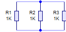
Grouping of resistors in parallel, image created by the author with the livewire simulator
CAUTION: Never do anything with electricity that you're not sure of, it's easier and less trouble to ask someone who understands.
Other recommended readings
Basic electricity / introduction
Basic electricity / DEFINITION OF ELECTRICITY
Basic electricity / Electicity Generators
Basic electricity / ELECTRICAL CONDUCTOR AND RESISTANCE
Basic electricity / Resistances, load and Ohm Law
Mulukutla S. Sarma. Introduction to Electrical Engineering
New York Oxford
OXFORD UNIVERSITY PRESS
2001
This post has been voted on by the steemstem curation team and voting trail.
There is more to SteemSTEM than just writing posts, check here for some more tips on being a community member. You can also join our discord here to get to know the rest of the community!
Thank you so much.! God bless you!
Hi @jesusjacr!
Your post was upvoted by utopian.io in cooperation with steemstem - supporting knowledge, innovation and technological advancement on the Steem Blockchain.
Contribute to Open Source with utopian.io
Learn how to contribute on our website and join the new open source economy.
Want to chat? Join the Utopian Community on Discord https://discord.gg/h52nFrV