What is a resistor and detail information's about it?
When we are curious about electricity and we have to know the first thing about electricity that is a resistor.
A resistor is a passiveElectronic_component. It is a type of two-terminal device and used in electric circuits.
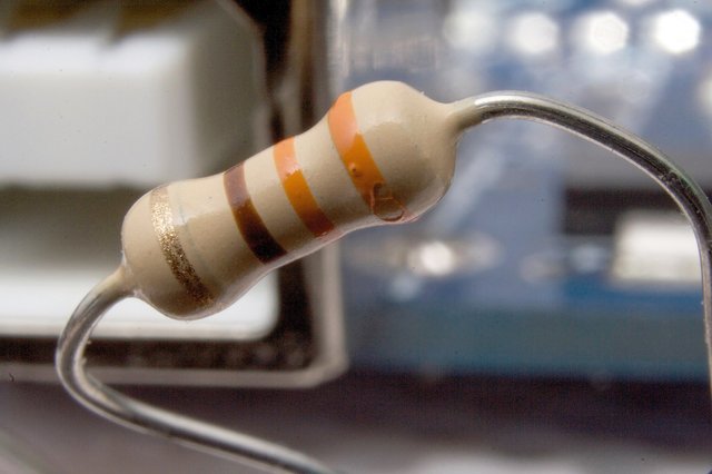 A typical axial-lead resistor Type:PassiveWorking principle:Electric resistanceElectronic symbol :

Its function is to prevent or obstruct the electric current. During the electrical circuit, the resistor prevents the flow by creating a potential difference between its two ends. Every circuit has use of a resistor. It is essential to make any type of circuits. It has Special work. We use resistors to reduce current flow in electric circuits to divide voltages, preference active elements and finish transmission lines, including other uses.
Electronic symbols and modulator
There are two typical designed diagram symbols like given below:
 |  |
In the first symbol(a) is a resistor (b) is rheostat (variable resistor) and (c) is potentiometer | and the second symbol is IEC resistors symbol |
The modulator to state a resistor's grade in a circuit diagram differs.One common design is the RKM code in consequence of IEC 60062.
It avoids using a decimal separator and replaces the decimal separator with a letter loosely associated with SI prefixes corresponding with the part's resistance. For example, 8K2 as part marking code, in a circuit diagram or in a bill of materials (BOM) indicates a resistor value of 8.2 kΩ. Additional zeros imply a tighter tolerance, for example 15M0 for three significant digits. When the value can be expressed without the need for a prefix (that is, multiplicator 1), an "R" is used instead of the decimal separator. For example, 1R2 indicates 1.2 Ω, and 18R indicates 18 Ω.
Theory of operation
 V, I, and R, the main parameters of O's formula.
credit:
V, I, and R, the main parameters of O's formula.
credit: Ohm's formula
In physics indicates the relation between electrical current, resistance and voltage difference. We know that if there is a difference between the two ends of a conductor, then the current flows through it. Depending on the quantity of this flow, depending on how much voltage difference has been applied at the two ends of the conduit, conductive and its temperature. George Simon O'Mahm gave the following formula about the connection between the electrical current flowing through a conductive wire and the voltage difference between its two ends, which is known as Ohm's formula.Statement of resistive circuits formula:
 V is a voltage source and R is a resistor through which the amount of electric current is flowing, according to the formula of Ohm's: V = IR.
credit: Wikipedia
V is a voltage source and R is a resistor through which the amount of electric current is flowing, according to the formula of Ohm's: V = IR.
credit: WikipediaIf the heat and other physical conditions are unchanged, the current through the conductivity of the conductor is proportional to the difference between the two ends of the conductor." If the temperature is stable, the electrical current through a conductor is proportional to the difference between the two ends of the conductor. Proportional means that if the difference between the two ends of the conductor is doubled, then the electrical current flowing through the conductor will be doubled. Again, if the difference between the two ends of the conductor is made to one-third, then the electrical current flowing through the conductor will also be one-third. Suppose V is a voltage source and R is a resistor through which I measure current flow, the resistive circuits, according to the formula:V=IR. In the field of physics, the formula refers to the difference between electrical current, resistance and voltage difference.
The formula can be expressed as follows:

Here, V = the difference difference between the two ends of the conductor, I = the electrical current, R = the resistance
The ohm (symbol: Ω) is the SI unit of electrical resistance, named after Georg Simon Ohm. An ohm is equivalent to a volt per ampere. Since resistors are specified and manufactured over a very large range of values, the derived units of milliohm (1 mΩ = 10−3 Ω), kilohm (1 kΩ = 103 Ω), and megohm (1 MΩ = 106 Ω) are also in common usage.
Series and parallel cercuits
An electric circuit can be set up in many ways. Electronic devices such as Resistors, Diodes, Switches etc. are placed in the structure and placed in the security framework. Such material placement circuit operation is extremely important, as different types of different setups create outputs, outcomes, or objectives. Two series of simple electronic or electrical connections and parallel circuits are called. These two are actually the most basic setup of all the electrical circuits but are significantly different from each other.
Basically, putting a series of inline circuits aims to have the same amount of current flow through all the components. This is a 'series' because these elements are in the single path of current flow. For example, when elements such as resistant are given to connect a circuit circuit, the same resistant is flowing through this resistor, but each has different voltages, that the amount of resistance estimates is unclear. The entire circuit voltage will be the sum of each component or resistor voltage.
Series Circuits:

A series circuit with a voltage source (such as a battery, or in this case a cell) and 3 resistors
VT = V1 + V2 + V3 ... is
it = I1 = I2 = I3 ...
RT = R1 + and 2 + R3 ...
Where:
Vt = Total circuit voltage
V1, V2, V3, and so each element = = it = Total current
I1, I2, I3, and so = across all elements = current
Rt = components / resistance to total resistance
R1, R2, R3, and So each element <= resistance value = another type of connection is called 'parallel'. Such a circuit element is not inline, or series, but parallel to each other. In other words, the elements are added in a separate loop. This circuit separates the current flow, and the current flow through each element will be combined to form the current flow of the source. The end of the material is the same as voltage; Poles are the same. Let's draw the same example given in series circuit and assume that the resistors are connected parallelly. Due to multiple connections, one of the 'parallel' circuits is 'multiple'.
And Parallel Circuits:
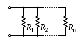 parallel cercuit
Credit : Author
parallel cercuit
Credit : AuthorVt = V1 = V2 = V3
Since it is = V (1 / R1 + 1 / R2 + 1 / R3)
1 / Rt = (1 / R1 + 1 / R2 + 1 / R3) One of the
main differences - In addition to the voltage, current and resistance sources, "The actual serial circuits will be broken if one element such as the barrier, burnt out; thus, the circuit will not be complete In parallel circuits, however, the effectiveness of other components will continue, since each component has its own circuits and is independent.
Summary:
- series circuit is the basic type of electric circuit which is all the components joined in a sequence so that the current through all of them is flawed.
- Parallel circuits have the types of circuits that simultaneously make voltages among all the components, depending on the current condition, based on their stability, or undeclared.
- If the circuit is in series, if an element of the series is burnt then the connection or circuit will not be complete.
- Parallel circuits will still continue to work, with at least the other components, if burned a parallel connected material.
References
- The resistor from Wikipedia "https://en.wikipedia.org/wiki/Resistor"
- Series and parallel circuits from Wikipedia "https://en.wikipedia.org/wiki/Series_and_parallel_circuits#Parallel_circuits"
- Ohm's law from Wikipedia "https://en.wikipedia.org/wiki/Ohm%27s_law"

gif credit: @foundation
This user is on the @buildawhale blacklist for one or more of the following reasons: