⚡ Control & Performance analysis of VSC-HVDC Transmission System:: Chapter-2:⚡HVDC TRANSMISSION
Introduction of HVDC transmission system:
There are two main ways for the transmission of large quantities of electric energy over long distances:
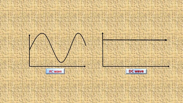
- High Voltage Alternating Current (HVAC)
- High Voltage Direct Current (HVDC)
Comparison between HVDC and HVAC:
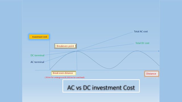
Investment cost:
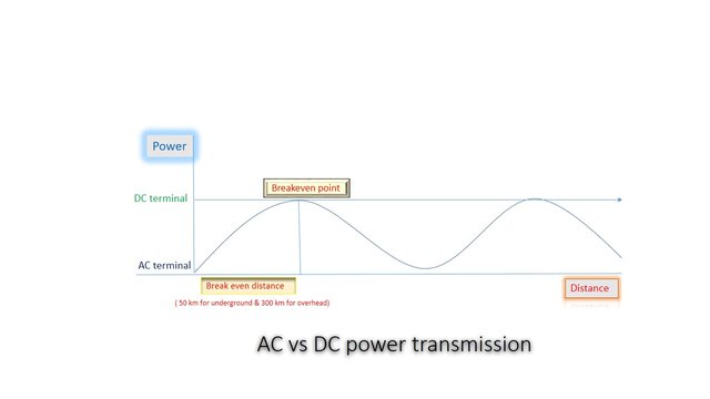
DC transmission requires fewer conductors than AC transmission - 2 conductors per DC circuit whereas three conductors per 3 phase AC circuit. HVDC allows line supporting towers to be smaller and, hence, requires lesser right-of-way. Thus, clearly, HVDC transmission line would cost lesser than an HVAC line. However, the terminal converter stations in HVDC are much more expensive which are not required for HVAC transmission. Over a specific distance, called as break-even distance, HVDC line becomes cheaper than HVAC. The break-even distance for overhead lines is around 300 km and for submarine lines it is around 50 km.
Losses:
Skin effect is absent in DC. Also, corona losses are significantly lower in the case of DC. An HVDC line has considerably lower losses compared to HVAC over longer distances.
Controllability:
Due to the absence of inductance in DC, an HVDC line offers better voltage regulation. Also, HVDC offers greater controllability compared to HVAC.
Asynchronous interconnection:
AC power grids are standardized for 50 Hz in some countries and 60 Hz in other. It is impossible to interconnect two power grids working at different frequencies with the help of an AC interconnection. An HVDC link makes this possible.
Interference with nearby communication lines:
Interference with nearby communication lines is lesser in the case of HVDC overhead line than that for an HVAC line.
Short circuit current:
In longer distance HVAC transmission, short circuit current level in the receiving system is high. An HVDC system does not contribute to the short circuit current of the interconnected AC system.
Application of HVDC Transmission:
⚪️Interconnecting national and regional grids:
When an island has to be connected to the main grid or asynchronous transmission systems separated by the sea have to be coupled, subsea cable HVDC is the solution. Siemens has already implemented several of these HVDC applications.
⚪️ Long Distance Transmission via overhead lines:
The most economical solution for DC transmission is interconnection via overhead lines DC overhead lines are HVDC applications that use more narrow transmission corridors for the same power transfer than compared to their AC counterparts and this is often a crucial issue for opting for DC transmission.
⚪️Bulk Power Transmission:
As the demand for electric power steadily rises, many existing AC transmission systems have already reached their capacity limits. At the same time, the share of renewable energy in the energy mix is growing. However, wind, solar, and hydropower is mostly generated far away from load centers This is why there will be a need for bulk power transmission corridors that can efficiently handle long-distance power transmission in the gigawatt range.
⚪️DC for Megacities:
Today cities mainly rely on AC grids. Using DC transmission for a city’s power in feed decreases overall transmission grid congestion and increases overall security and reliability of the electrical system in the area. It helps to meet the increasing power demand in an energy-efficient and cost-effective manner for the future
Different types of HVDC links:
HVDC transmission is economical for long distance power transmission, and for the interconnection of two or more networks that has different frequencies or voltages. For connecting two networks or system, various types of HVDC links are used. HVDC links are classified into three types. These links are explained below;
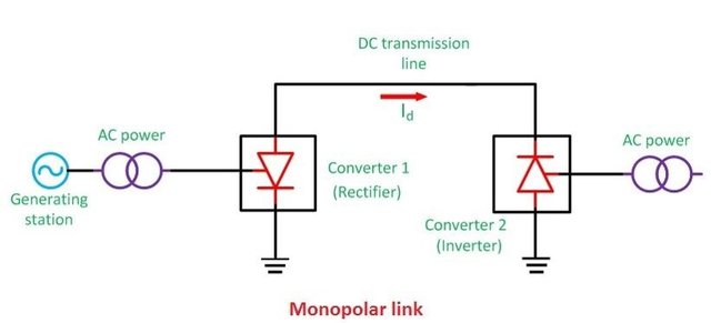
🔘Monopolar link :
It has a single conductor of negative polarity and uses earth or sea for the return path of current. Sometimes the metallic return is also used. In the Monopolar link, two converters are placed at the end of each pole. Earthing of poles is done by earth electrodes placed about 15 to 55 km away from the respective terminal stations. But this link has several disadvantages because it uses earth as a return path. The monopolar link is not much in use nowadays.
🔘Bipolar link :
The Bipolar link has two conductors one is positive, and the other one is negative to the earth. The link has converter station at each end. The midpoints of the converter stations are earthed through electrodes.
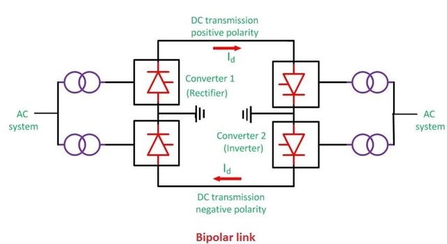
The voltage of the earthed electrodes is just half the voltage of the conductor used for transmission the HVDC.
🔘Homopolar link :
It has two conductors of the same polarity usually negative polarity, and always operates with earth or metallic return.
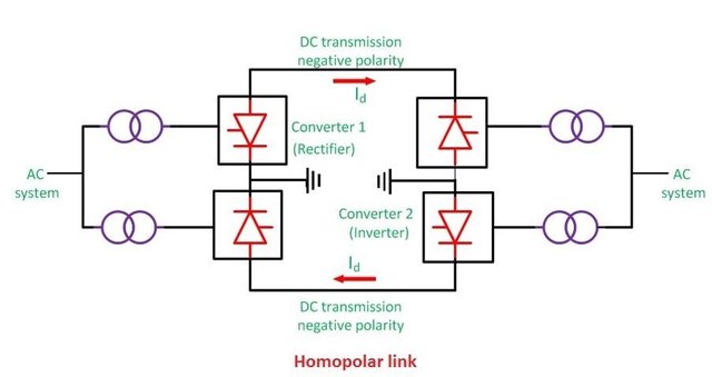
In the homopolar link, poles are operated in parallel, which reduces the insulation cost. The homopolar system is not used presently.
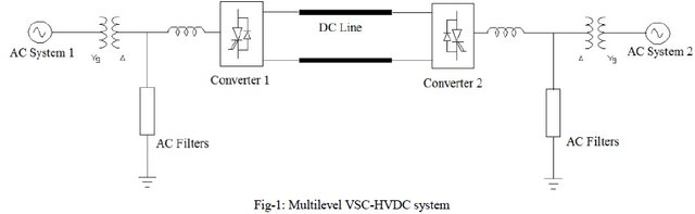
Voltage-source converters (VSC)
The development of higher rated insulated-gate bipolar transistors (IGBTs), gate turn-off thyristors (GTOs) and integrated gate-commutated thyristors (IGCTs), has made smaller HVDC systems economical. The manufacturer ABB Group calls this concept HVDC Light, while Siemens calls a similar concept HVDC PLUS (Power Link Universal System) and Alstom call their product based upon this technology HVDC . They have extended the use of HVDC down to blocks as small as a few tens of megawatts and overhead lines as short as a few dozen kilometers. There are several different variants of VSC technology: most installations built until 2012 use pulse-width modulation in a circuit that is effectively an ultrahigh-voltage motor drive.
AC side filter:
Filter circuits are required to absorb the harmonic currents to such an extent that the residual currents which flow into the network do not cause any unacceptable voltage distortions or telephone interference. Harmonics in AC system causes overheating, losses, interferences in communication line. Malfunctioning of operation, over voltage due to resonance and instability in control system. Filters involved in VSC is cheaper as compared to classical HVDC and PWM technique reduces the harmonic content to a great extent.
Phase Reactors:
It has advantage like preventing high frequency harmonics in AC line current as it acts like a low pass filter. Restricts the change in current in direction through the IGBT switch.it provides a decoupled control of real and reactive power by controlling the current through it.Transformer:
A transformer is a device that is used to either raise or lower voltages and currents in an electrical circuit. In modern electrical distribution systems, transformers are used to boost voltage levels so as to decrease line losses during transmission.it act as like a barrier between AC and DC side. A two winding transformer can be used for VSC converter.it is not need to block the DC component.
Summary:
This chapter summaries the VSC-HVDC transmission, comparison between HVDC and HVAC. The application, configuration and classification of HVDC is discussed. VSC-HVDC model is described.