Everyday Electronics part #5: The Silicon Controlled Rectifier (SCR); the thyristors and triacs
Welcome to this exciting series of everyday electronics where I get you very close to electronics components, their use and how to recognize them.
))
[thyristor symbol credit: wikimedia Creative commons license. Author: ruthenensis]
Its been a while I updated this everyday electronics series and this time around I promise it's gonna be even more exciting. Today I will be talking very much about thyristors and triacs which are both rectifiers and they're not very popular electronic component.
In order to understand and appreciate today's everyday electronic series, I will like to first explain what is rectification and why it is very important and the concept of diode and its operation.
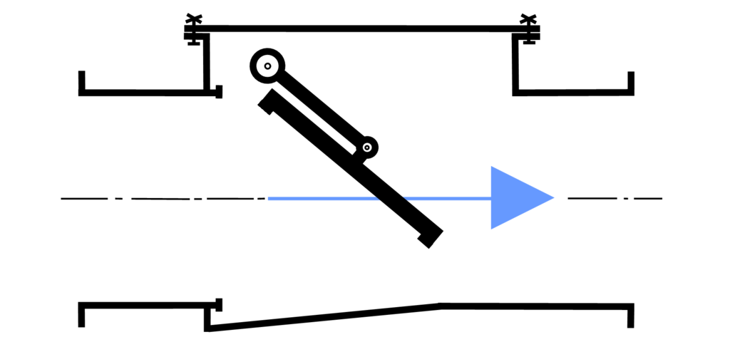
I will like to explain the concept of rectification using the concept of check valves since most of us are physicists. The operation of rectifiers which offers rectification is very much like the operation of the hydraulic check valves. Hydraulic check valves are mechanical equipment which allows the flow of liquids in one direction.
They are pressure operated which means that they allow the flow of fluid across them only if the incoming fluid is of the right “polarity”. Polarity here means that if the gate is designed or placed to open towards the left direction, any fluid moving from right to left is allowed to pass and hence is said to be in the correct polarity while fluid pressure tending towards the right direction is prohibited by the gate.
[credit: Wikimedia. A creative commons license. Author: KaHe]
Same thing with rectification, a rectifier is a device that limits the flow of current to only one direction by allowing current of certain polarity to pass. By so doing, it has the ability to convert alternating current to direct current. Our phones and laptops only charges with the help of direct current but the output of our wall sockets at home is an alternating current, hence our chargers functions by converting this alternating current into direct current using rectifiers and other current and voltage smoothing components.
The Diode and its operation
Calling diodes rectifiers outright might be wrong since the term rectifier is used for devices that handles current above 1 ampere while diodes are designed to operate withing the range of not more than 1 amps. Hence diodes are semiconductor devices which operates using the principle of rectifiers.
))
[credit: Wikimedia A Creative Commons Attribution-Share Alike 3.0 Unported, 2.5 Generic, 2.0 Generic and 1.0 Generic license. Author: Omegatron]
The symbol of the diode is shown on the left. The direction of the arrow is misleading as electron actually is allowed to flow in the opposite direction no thanks to the initial designers who adopted the symbol by considering that current flows from positive end of the circuit to the negative end of the circuit. Just like the check valve described above, the diode allows current to move in one direction and just like the check valve is driven by fluid pressure, the diode is driven by applied voltage.
Consider the two circuit diagrams shown below. For circuit A, current successfully moves from the positive end of the battery to the to the negative end thereby powering the load (the light emitting diode). In the setup of the first circuit, the diode is said to be in a forward biased mode this is because the positive end of the diode corresponds to the positive end of the battery and this arrangement allows current to flow. Also note that there is a movement of electron in the opposite direction as indicated in the drawing.
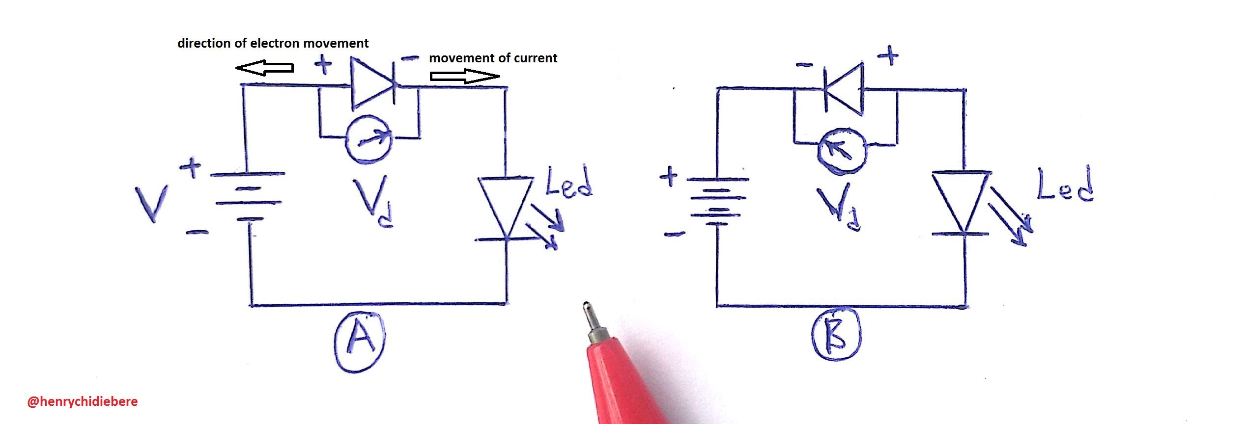
circuit designed by me using free hand and windows paint
The same is not applicable in the second circuit as the polarity of the diode has been changed in reverse order. With this arrangement, the light emitting diode will fail to come on because just as the check valve does not allow fluid to flow in both directions, the diode is said to be reverse biased and no current is allowed to flow in this arrangement.
This is so because when the diode is forward biased, there is little (almost negligible) voltage drop (Vd) across the terminals of the diode. Hence, most of the battery's voltage freely flows across the the diode because the diode is acting as a current conductor. The reverse is the case when the diode is reverse biased as there is very high voltage drop (almost all the battery voltage) across the terminals of the diode making the diode act like an insulator.
The diode is able to act both as a conductor and as an insulator because as a semiconductor device, it is composed of holes (positive charge) and electrons (negative charge) and a depletion region. The picture of a real diode shows a black component with a shiny painting towards an end. The shiny painting indicates the pointy end shown in the symbol and this is the most negative end or the cathode leaving the opposite end as the positive terminal or the anode. The diode (and subsequently, the thyristor and triac) are constructed by joining two or more semiconductors usually of the negative type (N-type) and of the positive type (P-type).
This is why the diode is known as the P-N junction diode. The N-type semiconductor contains very little amount of hole but very high amount of electrons while the P-type semiconductor contains very little amount of electrons but very high amount of holes. The space between these junction is called the depletion region.
This region is called depleted region because at the junction of the P-type and N-type semiconductor, the positive charge (holes) in the P-type material attracts electrons from the N-type material (Unlike charges attract) making a portion of the N-type material to loose electrons and become a bit positively charged (intrinsic) semiconductor. The same thing happens at the positive end of the semiconductor material.
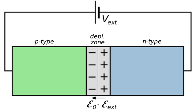
[Movement of electron and holes in a forward biased diode. Credit: Wikimedia. A creative commons license. Author Inductiveload]
This size of this depletion region can change depending on the type of voltage applied at the terminals of the diode. When the diode is in reverse biased mode, the depletion region increases to much due to the fact that unlike charges have been applied to both terminals which makes the hole move farther away from the depletion region towards an even closer electron (at its terminal) and the electrons moves farther away from the depletion region leaving even more space in the depletion region.
The reverse is the case when the diode is forward biased as like charges are applied to its terminals which makes the holes to move towards the depletion region and the electrons also moves towards the depletion region thereby closing the gap at the depletion region. This implies that at forward biased mode, the diode is completely closed and current can flow.
At this point, I will assume we all can identify a diode and even go as far as explaining its operation, hence lets head straight to today's topic, thyristor.
The thyristor and its operation
Do you wish to control your high powered AC circuits with a better switch? Do you wish to carry out some form of phase control for your AC circuit? Then, the thyristor is here to help. It can drive circuits in kilowatt range making it a better switch than a typical relay in your circuits. The thyristor is basically a P-N junction device whose operations are controlled using a gate. Unlike the diode that has just one P-N junction, the thyristor has more than one P-N junction making it a three-terminal device instead of two-terminal, like the diode.
A diode is either in its forward conducting state or reverse blocking state but the thyristor has another state called the forward blocking state. In the forward blocking state, the component is “partially” conducting current at both terminals but there still exists a depletion region between the junctions.
Consider the hand sketch I made below, the thyristor consists of three depletion regions labeled A, B and C. By virtue of my previous explanation of diode, it is obvious that when positive end of the thyristor (anode) is connected to the negative end of power supply, and the negative terminal (cathode) connected to the positive end of the power supply, the thyristor is said to be reverse biased and all the three depletion regions are wide enough to function as an insulator, hence there is no current flow in the circuit.
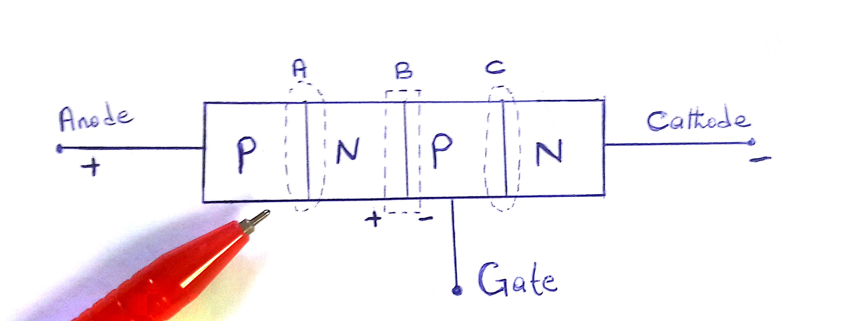
When the connection is reversed (i.e, forward biased) the depletion regions A and C, reduces and hence can conduct current. This is called the forward blocking state of the thyristor because though the component is forward biased, current would still not flow due to the presence of the depletion region B.
The thyristor will only be in forward conducting state if and only if a positive voltage is applied to the gate. At the forward blocking state, the polarity of the depletion region is shown; the depletion region at the N-type material is more positive while the depletion region at the P-type material is more negative. This can be seen in the above image. When positive voltage is applied at the gate, the depletion region B disappears thereby making possible for current to flow from the anode to cathode.
Unlike the diode that goes back to its initial state when voltage is removed from its terminals, the thyristor continues in its “on” state even after the gate current has been removed until the current in its anode and cathode goes below a certain value called the holding current. This phenomenon is called latching. Thyristors don’t go off easily once it comes on and this makes it not applicable in high frequency circuits switching.
))
[thyristor current voltage graph credit: wikimedia A creative commons license. Author: Mikhail Ryazanov]
Consider the graph shown on the right, on the left side of the graph, the thyristor is behaving exactly like the diode and is said to be in reverse blocking state. It will keep being in this state until the reverse breakdown voltage (Vbr) is exceeded. This is seen on the right side of the graph. Once the Vbr is exceeded, the thyristor is said to be in forward blocking state and will not conduct current until an appropriate latching current Il is applied to the Gate terminal.
As the gate current Ig increases from zero to a value far greater than zero (Ig >> 0), the thyristor will be in full conducting state just like a diode in a forward biased mode.
To really grasp how thyristors works, let's carry out a simple sine wave phase control circuit.
Practical application of thyristor
Consider the circuit shown below which consists of an AC power supply, a resistive load a variable resistor, a thyristor and a diode (normal diode). I am using a resistive load in this example because thyristors doesn’t do well with inductive load due to power factor issues and the ability of the thyristor to latch at the peak of the AC current which could result in power surge problems.
))
[circuit designed by me]
When the AC power is allowed to flow, a full power cycle goes to the load and the resulting waveform is in the form of a pure sine wave. This is the behavior of the circuit without the thyristor circuit.
Now considering the thyristor circuit, by default, only the positive half cycle of the AC current will flow to the load (a connection of oscilloscope at the terminals of the load would confirm this). And the waveform will look like the waveform labelled “A” in the picture below. The purpose of the diode connected at the gate “G” of thyristor is only to ensure that only positive voltage is allowed to get to the gate.
))
To determine the minimum and max amount of current that can drive the gate we can check the datasheet of the thyristor we are using (I used NTE 5569 during my project which had minimum gate current IG of 50mA). This is essential to so as not to allow excess current into the gate. The amount of current flowing to the gate is given by ohm’s law:
IG = V/R
Hence the current can be varied with the help of the variable resistor. At the minimum value of resistance offered by the resistor, the waveform will be of the shape “A” above. As we increase the resistance of the variable resistor, the amount of time required for the thyristor to latch and un-latch also increases thereby shaping the phase angles of the AC current ash shown in “B” and “C”
Summary
Transistors and diodes can be a very good and fast switch but they can't survive large amount of current. Relays are also good mechanical switch which can withstand very huge amount of current but just like most electro-mechanical system, it can be slow and have inherent contact issues. The thyristors are not fast switches but are more precise than relays and can withstand kilowatts of electrical power.
Only the positive half cycle of current passing through a thyristor makes it out of the thyristor, hence to negative half cycle of another thyristor is required. combination of these thyristors gives rise to what is called Triacs.
REFERENCES
- How thyristors works -explainthatstuff
- Thyristors-Wikipedia
- Diodes and thyristors -southampton
- Thyristor Theory and Operation -radio-electronics
- Triacs-radio-electronics
If you write STEM (Science, Technology, Engineering, and Mathematics) related posts, consider joining #steemSTEM on steemit chat or discord here. If you are from Nigeria, you may want to include the #stemng tag in your post. You can visit this blog by @stemng for more details. You can also check this blog post by @steemstem here and this guidelines here for help on how to be a member of @steemstem. Please also check this blog post from @steemstem on proper use of images devoid of copyright issues here.

How do thyristors work in electronics?
nice post.
Thyristors are basically high powered devices but they're very good replacement for relays in both electrical and electronic circuits and are very good in wave shaping of AC circuits just as I explained above. Thanks for your time.
Exactly thanks
Another great installment, Keep it up!!
You know i might just find this material handy in the course i am presently taking on power electronics.
Kudos!!!
wow, then I'll be happy to help