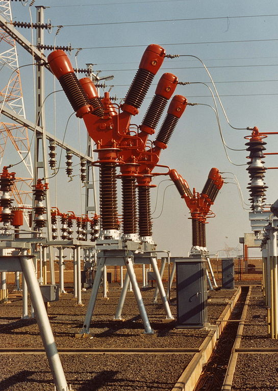
Challenges of Power System Protection-The Way Out
Power system networks and components are not entirely immune to faults or by attacks as a result of vandalisation. Faults are bound to occur in electrical equipment or apparatus due to ageing or exposure to adverse environmental conditions which could lead to degradation of the insulation. Once there is deterioration in the insulation between electrical conductors, between electrical conductors and earth or any earthed screen surrounding the conductor, the current will leave its intended path and deviate into non-current carrying elements of the installation. This current diversion to unintended paths constitutes a hazard and could expose individuals to risk of electric shock.
The deterioration of insulation strength on itself cannot be viewed as a fault until it initiates an abnormal effect on the system. This abnormal effect can present itself in the guise of flow of excessive current, in the lowering of the impedance between conductors or between conductors and earth to a value much less than the lowest low impedance consistent with the particular circuit under consideration.
In an electrical power system consisting of generators, transformers, switchgear, transmission and distribution circuits, it is just a matter of time before a there is a failure in a part of the power system. A power system could be viewed as a chain, and a chain is as strong as the weakest link and as such failure is inevitable.

The likelihood of failure or occurrence of the abnormal condition is more on power lines, and this is understandable owing that the power line spans several kilometres with different auxiliaries like the cross-arm, insulators, towers, lattice towers and any one of these members can fail. Any failure of each link will have a ripple effect which will spread to other links thereby crippling the system. Also, we must appreciate that the transmission lines are exposed and must operate under variable weather conditions and this could impose duties on the transmission lines and its parts.
Published statistics revealed that an average of about 63% of power system fault occurs in overhead line and cable circuits, 14.5% on transformers and reactors, 13.5 % on generators while the remaining percentage is shared between bus-bars, switchgear and other equipment of the power system.
The most significant effect of faults is the interruption of supply.
We have already discussed the different causes of faults in my previous post. One of the ways of securing the transmission line from the incidence of overvoltages which could result from switching is to provide high insulation up to the level of 3 to 5 times the nominal value of the voltage although the pollution of the insulation string tends to cancel the effect of the extra insulation introduced.
Lightning generates high voltage surge in the power system of value hovering around millions of volts and the feasibility and economics of providing such level of insulation which can absorb the effect of such abnormality is not viable. These surges move almost at the speed of light, and the limiting factors include the impedance of the system and the line reactance.
The only way out in which the fault can be reduced to the barest minimum lies in the improvement of the quality of the design, using good quality equipment and maintenance culture.
It is worthy to keep in mind that there is no way of eliminating the fault completely.
If the protection performance of a power supply system is evaluated periodically, based on recorded statistics, the shortcomings and the weak links of the system can easily be identified, checked and rectified.
System failures and power cuts can be minimised by reinforcement of protection, automation, information and control of equipment. The system should have schemes put in place that will pinpoint the exact location of fault which will have the effect of reducing the overall interruption time in the event of a fault occurring in the system.
This fault location scheme will improve the quality of power supply and its reliability.
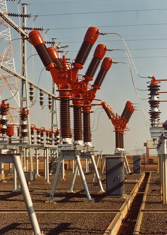
The major uses of the results of fault analysis are for the right choice of switchgear and choosing the appropriate setting of protective relays, both being housed in substations. Incidentally, the design of all items in an electrical plant is influenced by the knowledge of fault conditions. Circuit-breaker ratings are determined from the fault currents that may flow at their particular locations in the event of a fault and are expressed in kA (fault current flow) or MVA (short-circuit level).
The maximum circuit-breaker rating is in the range of 50 000–60 000 MVA per phase. The circuit breaker must be capable of extinguishing the fault-current arc and at the same time withstand the considerable forces set up by the short-circuit currents, which can be considerably high. Having the idea of the currents which may arise from various types of fault at a location is paramount for the efficient specification and setting of system protection.
Faults on a power system result in high currents and may likely cause the individual generators in a power station, or groups of generators in different stations to lose synchronism and fall out of step which may tear the system apart.
To avoid loss in synchronism, we must devise a way to remove the fault from the system as quickly as possible. The quick removal of fault from the system necessitates the deployment of automatic means, to detect abnormal currents and voltages and, when detected, to initiate the opening of appropriate circuit breakers. The protection scheme must achieve this fit.
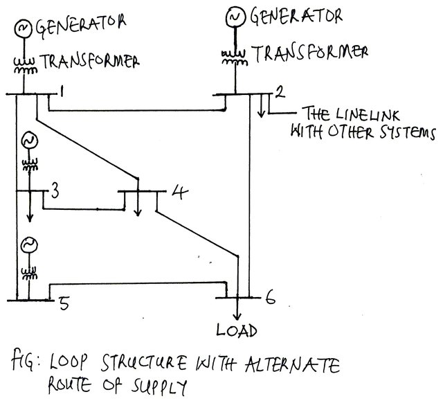
In an extensive interconnected network, consisting of many generators and alternate routes, considerable design knowledge and skill is required to isolate the faulty part of the system and leave the healthy section working without interruption.
Fuse Cutouts
A fuse is essentially a fused disconnecting switch. A fuse consists of a short piece of metal having low melting characteristics, which will melt at rated temperature. The fuse may be placed to cut out the section of the circuit, which is endangered, allowing the rest of the circuit to remain energised. A primary cutout fuse is connected between the primary lines and the transformer to protect the transformer from overloads and to disconnect the transformer from the primary lines in the event of a fault.
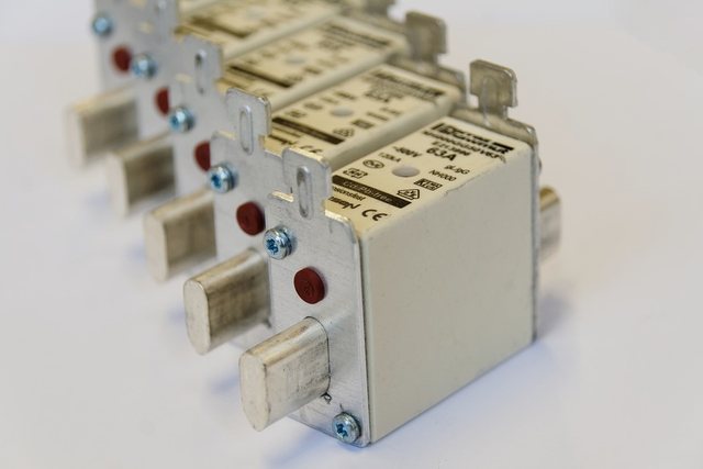
Cutouts are relatively cheap and have the disadvantage that the fuse link must be replaced every time it blows, which often produces a relatively long outage. A burnt out fuse link must always be replaced by another having the same rating.
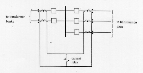
There are different varieties of automatic protective systems, ranging from simple over-current relays to elaborate systems transmitting high-frequency signals along the power lines. The simplest but extremely effective form of protection is the over-current relay which works in tandem with the circuit breaker. The over-current relay by closing its contacts energises the circuit-breaker opening mechanisms when fault currents pass through the equipment.
.png)
It is hard to talk about circuit breakers and relays without mentioning Instrument transformers which are made up of voltage (potential) and current transformers. The output of instrument transformers goes the measuring devices and to the relays. Instrument transformers give an output of either a current or voltage at a lower level to monitor the voltage or current in a given circuit that is at a higher voltage.
The instrument transformers are connected to the high voltage line and provide an output that is a much lower equivalent of voltage and current which is precisely proportional to its input.We are aware that if we are to channel the high voltage and current to relays for measurement, it will not be economical in the sense that relays that will handle such voltage will be of a bigger rating, cumbersome and costly.
The protection used in a network can be viewed as a form of insurance in which a small percentage of the total capital outlay is set aside (about 5%) to safeguard the power system equipment to ensure the continuity of operation of the power system in the event faults.
Protection in power system function as to remove as speedily as possible any element of the power system which has developed a fault. It is essential to a power system engineer to remove as speedily as possible the faulty part from the rest of the healthy section. This approach is important to avert any of the following:
- The fault if not quickly isolated is likely to split the system by throwing the generators in the system out of synchronism.
- There is the risk of damage to the affected plant.
- There is also the risk that the fault will spread to the healthy section which could cause damage to the healthy plants.
In developed economy or highly industrialised society, the maintenance of continuity of supply to consumers is of the highest priority, and the adequate provision of protection systems is essential.
The protection system should be discriminative in the sense that it should possess the ability to select and to disconnect only the faulty section or element in the power system while leaving all others (healthy section) in normal service as long as that is achievable.
In providing selective fault clearance, there is need to furnish the protective device with information regarding its legitimate zone of protection to enable the relay to discriminate between fault condition within its zone of protection and those outside its jurisdiction. Once this is established the relay will only operate for faults within its zone of protection and would only actuate the circuit breaker closest to the fault it wants to isolate and as a result leaving the sound section only in normal operation.
Conclusion
In summary, the relay must initiate the automatic tripping (opening) of associated circuit breakers to isolate faulty equipment so that the rest of the system can continue to operate successfully; and to limit damage to equipment caused by overheating and mechanical forces. This applies to large networks or transmission systems. In the LV distribution system, the primary function of protection is to maintain continuity of supply.
To achieve 100% uninterruptible supply is not certain in practice. The way out of this dilemma is not only reliant on installing high-quality protective devices but also in ensuring there are alternate routes in the power system and distribution networks having duplicate or multiple outlets from power sources to load centres while ensuring at least two of sources of supply (feeders) to each distribution station.
It is only a matter of time before there will be need to protect the system from inevitable fault. And this is taken care by functional protective system capable of isolating the faulty part of the system while leaving the sound section in service.There is also need to have alternative route I'd supply so as to increase the security of the system and reliability. Thanks once again for doing justice to the topic.
Thanks for making out time to visit my blog. It feels good to know you appreciate the effort made in putting together the post.
Being A SteemStem Member