Transformers and Its Impact on Modern Life
The word transformer is a household name in my village, and it means different things to different people. If my kinsman should define it, he would probably say it is a device that quickly breaks down and takes so much time to repair or replace. You can’t blame him because we have experienced series of power outages in the past due to transformer breakdown and some lasted up to a year before it was restored.

And when you are from this part of the country you would agree with me that its popularity has nothing to do with delivering its duties. Its popularity is due to the frequent breakdown of the transformers with accompanying power outages caused by overloading.
There is hardly a village or community where there is appropriate power system planning. People will build a house and hook it to the nearest electric pole without, the consent of the power utility company. Transformers are rated in KVA, and as such, there is a level of sustained overload it cannot take.And in these areas, the primary source of the power outage is burnt out transformer coils due to overload.
Many consumers’ have no records with the utility company, but that does not stop them from consuming power. They elicit the services of road-side electricians to connect them illegally to the power system network since there are no smart meters or sensors to signal the utility for such illegal connections. Such is the way the system is loaded without the knowledge of the power company.
Overhead lines can easily be monitored by linesmen to establish when there are illegal tappings. Unfortunately, even when the linesmen dictate such pilfering, they hardly report it. They take advantage of it by agreeing with such dubious minds to pocket maybe half of what the estimated bill themselves, shortchanging their company. In the end, the utility and the masses will bear the brunt of such act.
The first power distribution system was invented by Thomas A. Edison in the United States. It was a 120-V dc system designed to supply power for incandescent light bulbs. The first central power station built by Edison came into operation in New York City in September 1882.
This system suffered from substantial power losses because it transmitted power at low voltage and therefore requires high current to be able to transmit a significant amount of power. These high currents caused heavy voltage drops and power losses in the transmission lines, tremendously limiting the service area of a generating station. To avert this heavy power loss, they resorted to locating the central power stations every few city blocks.
The low-voltage dc power systems could not be used for long-distance transmission owing to heavy line losses; this drawback resulted in the localization of generating stations. They were mostly inefficient because they were built in a small capacity.
.
The invention of the transformer and the subsequent development of ac power sources gave birth to high voltage ac transmission with the advantage of minimal power losses in the transmission lines.
An ideal transformer (lossless) changes one ac voltage level to another voltage level without altering the actual power supplied. If a transformer steps up the voltage level of a circuit, it must suppress the current to maintain that the power into the device equal to the power out of it.
This attribute of the transformer enables ac electric power to be generated at one central location; its voltage stepped up by a unit transformer for transmission over long distances at very low losses. When it gets to the low voltage substations, it would be stepped down again depending on the need of the consumer.
The transmission losses in the lines of a power system are proportional to the square of the current in the lines, therefore, raising the transmission voltage and reducing the accompanying transmission currents by a factor of 10 with transformers reduces power transmission losses by a factor of l00. Transformer facilitated and enhanced the way we use power.
A transformer is a device that changes ac electric power at one voltage level to ac electric power at another voltage level through the action of a magnetic field. It consists of two or more coils of wire wrapped around a standard ferromagnetic core. These coils are (usually) not directly connected. The only connection between the coils is the common magnetic flux present within the core.
One of the transformer windings is connected to a source of ac electric power, and the second (and perhaps third) transformer winding supplies electric power to loads. The transformer winding connected to the power source is called the primary winding or input winding, and the winding connected to the loads is called the secondary winding or output winding. If there is a third winding on the transformer, it is called the tertiary winding.
In a modern power system, and in Nigeria precisely, electric power is generated at voltages of 10.5-16KV. The unit step-transformers step up the voltage to 330 kV for transmission over long distances at very low losses. The voltage of 330KV is called primary transmission voltage. There are sub-stations along the line, and it will get to where the voltage will be brought down to 132KV by a step-down transformer. The 132KV is called secondary transmission voltage.
Consider the power system layout diagram below:
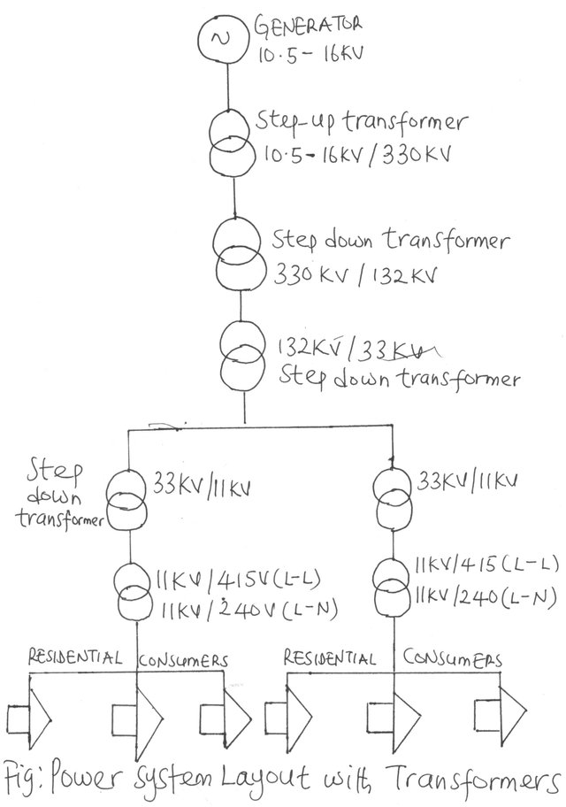
The primary distribution commences at the next transformer sub-station where the voltage will be reduced to 33KV.
The voltage is further stepped down to 11Kv, and this is the secondary distribution voltage. Consumers taking large amounts of power up to and above 500KVA may be supplied directly from the secondary distribution network.
The bulk of the consumers are supplied majorly from the tertiary distribution because their load is much smaller.
A typical classification of the different voltage levels along the line of power system in Nigeria is as tabulated:
Primary Transmission 330KV
Secondary Transmission 132KV
Primary Distribution 33KV
Secondary Distribution 11KV
Tertiary Distribution 415L-L; 240 L-N
TYPES OF TRANSFORMERS
The principal purpose of a transformer is to convert ac power at one voltage level to ac power of the same frequency at another voltage level.
Transformers are also used for a variety of other purposes (Instrument transformer which is of two sub-division: voltage transformer and the current transformer, impedance transformation). We will consider every one of these uses the transformer can serve
Purpose of Instrument Transformers
Instrument transformers provide either a current or voltage at a level proportional to the equivalent high voltage or current in a given circuit.
VOLTAGE TRANSFORMER(Potential Transformer)
It is more economical to construct protective equipment at a lower voltage to monitor high voltage lines or equipment than building such equipment at a voltage level equal to the rating of the equipment being protected. The Voltage transformer is used for voltage sampling and can be referred to as potential transformer.
For example, it would be expensive build an ammeter to a capacity that would measure 500 amps in a conductor directly. It would be better and more economical to have an equivalent ammeter to measure current over a range of 0–5 amps.
By incorporating a current transformer in the circuit, it will step than the current at precisely a value proportionate to the current in the conductor that needs to be monitored within a range of 0–5 amps which correspond to 0–500 amps. The ammeter will be calibrated or designed to have a scale of 0–500 amps.
Based on the same argument, it would not be economical to measure a voltage of 11,000 volts directly. A more feasible way would be to insert a voltage transformer in the circuit to step down the voltage to a value directly proportional to the equivalent high voltage being monitored. The calibration over a range of 0–110 volts will enable a lower rating protective device which would ensure lower cost of protective devices and relays.
The 0-110 volts calibration of the potential transformer is proportional to 0–11,000 volts. Current and voltage transformers are also employed to provide the energy needed to operate various protective relays. The degree to which an instrument transformer produces a current or voltage that is proportionate to the one to be monitored or measured is referred to as its accuracy.
CURRENT TRANSFORMER
As the name indicates, current transformers are used to step down current in a known and accurate proportion concerning current and phase. For example, if there is any need to measure the current being drawn by a vacuum cleaner to determine if it is faulty or not. You must, first of all, establish the voltage level of the motor circuit. From the information gotten you can determine the level of insulation, the current transformer should have.
APPLICATION OF INSTRUMENT TRANSFORMER
• The electric utilities, independent power producers, or industrial users utilise it in moderating the voltage and current to the level in which the operation of revenue metering device will be economical.
• It inserted in the circuit to step down the voltage/current before the protective relays acts on the resulting signal to establish when there is an anomaly before actuating the circuit breaker to trip in the event fault
• It facilitates high accuracy current range used for independent power facilities
• It caters to all the protective, measuring and control gear for the station service power needs within substations or power needs at remote sites
IMPEDANCE MATCHING CAPABILITIES OF TRANSFORMERS
For delivering maximum power to a system, the impedance of the system should be matched to that of the source.
Transformers are used for this purpose, and, this achieved by altering the turns ratio of the primary and secondary winding of the transformer.
Let us say that the impedance of the load is Z. We can connect it to the secondary of the transformer, and calculation can establish total impedance seen by primary side. The impedance will be a function of turns ratio of windings of the transformer.
Note that the impedance of the system is fixed, but by changing the turns ratio of the transformer we can change the net impedance seen by or referred to primary in such a way that it will match. Neither the impedance of the load nor that of the system is changing.
CONSTRUCTION OF TRANSFORMERS
Power transformers are constructed on one of two types of cores. They are:
• The core type and
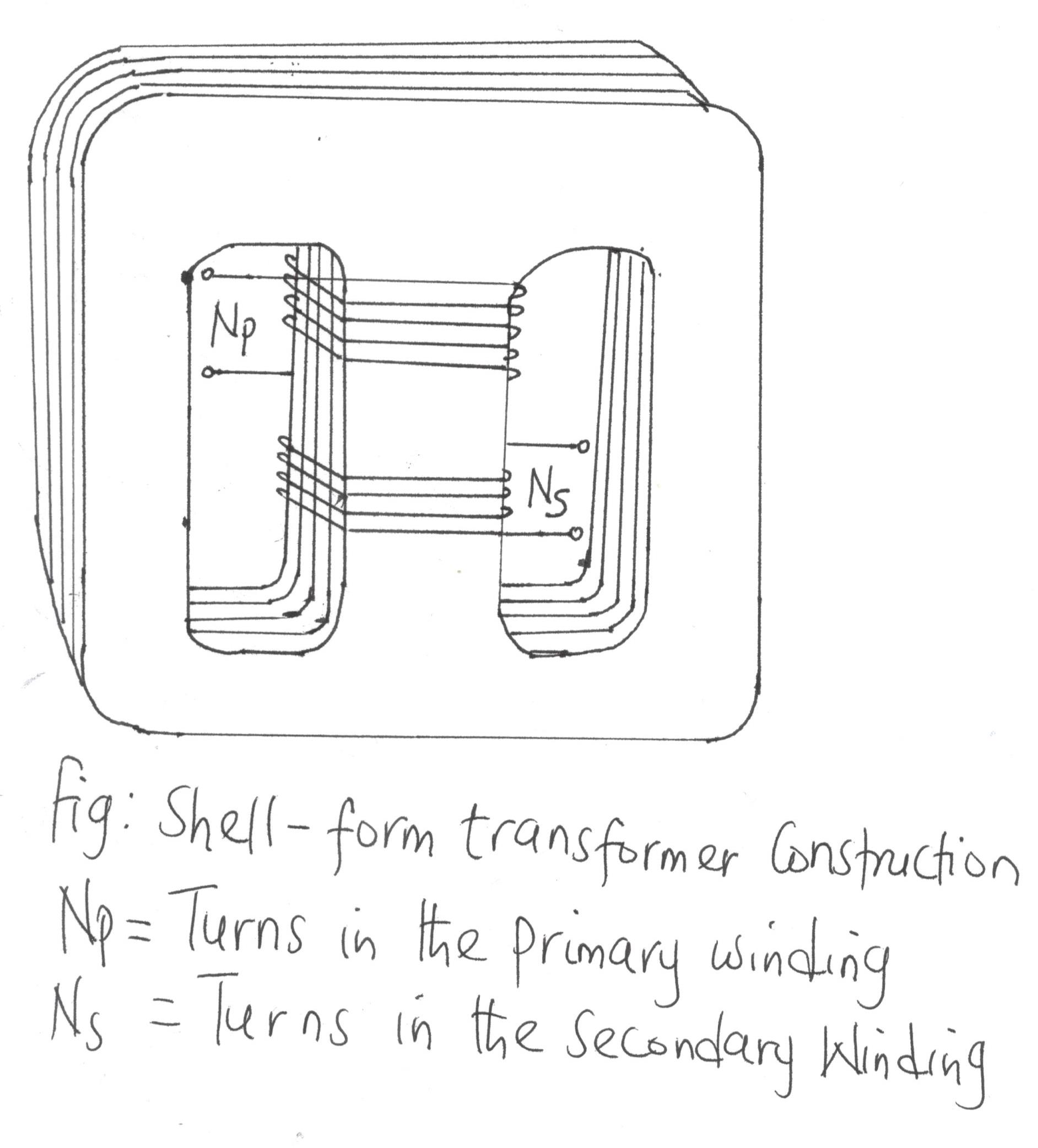
• The shell type
The core type consists of a simple rectangular laminated piece of steel with the transformer windings wrapped around two sides of the rectangle.
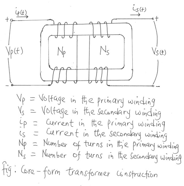
The core of either the core type or shell type is constructed of thin laminations which are electrically isolated from each other to minimize hysteresis eddy currents and eddy current losses.
The primary and secondary windings in a physical transformer are wrapped one on top of the other with the low-voltage winding innermost. The reason for such an arrangement is to:
- It solves the problem of insulating the high-voltage winding from the core.
- Because of the proximity of the windings, a stronger flux is established, and with little leakage, thus a better mutual coupling is achieved.
The second type is the shell type which consists of a three-legged laminated core with the windings wrapped around the centre leg. It is illustrated in the figure below:
The purpose often determines the name given to a power transformer.
A transformer connected to the output of a generator and is used to step the voltage up to transmission levels (330KV) is often referred to as a unit transformer.
The one at the other end of the transmission line, which steps the voltage down from transmission levels to distribution levels (from 132KV to 33KV), is called a substation transformer or distribution transformer.
Finally, the transformer that steps down the voltage from the distribution voltage to the final residential voltage at which the power is utilized (220L-V, 415 L-L) is called a distribution transformer.
All these devices are primarily the same- the only difference between them is the duty they are called to perform.
CONCLUSION
The invention of the transformer and the consequent development of ac power sources removed the limit on the range and power level of power systems. The power transformers have made it possible for a generator to be located where the natural condition specific to the type of generator favours it most. The choice to locate the generator anywhere is with the knowledge that power can easily be transported to the load centres or consumers with minimal losses with the aid of high voltage transmission lines.
This high voltage transmission is achieved with unit step-up transformers which steps the voltage up while suppressing the current to reduce I2R losses.
REFERENCES
Transformers can either step up the voltage or step it down at the same frequency, while the power input will be equal to output power. Thanks for sharing.
The functions of transformers are quite numerous but that of instrument transformer is very crucial. This is because the protective relays and other measuring and control devices relies so much on the current and potential transformers fo perform their duty. That is understandable when you consider that in high voltage system, the relays if built to measure directly will be somewhat bulky and expensive. The only way out is to get a proportionate voltage and current equivalent to the one being measured and this is achieved using instrument transformers. Thanks for sharing.
You are right about the economics of using instrument transformers as opposed to designing a high voltage protective, measuring and control gears which apart from being bulky and expensive but may subject operators to high voltage and exposure to greater risk. Thanks for your time.
Transformers have removed the constraint placed on the voltage level that could be transmitted at any given time and as such gives the power system planner free hand to choose the most appropriate location for his power station.
This is possible because power can be generated far from consumers and transmitted at high voltage to the load centers with minimal losses.
Thanks for highlighting other uses to which transformers can be put. I always get something new from your posts.
Thanks for your input. Since the advent of transformer, matching the impedance of a system to a load for maximum power transfer is easily achievable. Transmission at high voltage has improved the maximum power that can be transferred over a given transmission line. Your input will always be valued. Thanks for visiting my blog.
You might find it interesting that it was Nikola Tesla that invented AC current, opening the door to our current power distribution system.
It will not change your current studies, but you might find a look into Nikola Tesla interesting. I'm enjoying your posts.