Arduino Project: Build a Push Notification device for Washing Machine

Github Repository
What Will I Learn?
- You Learn about Arduino
- You learn how to create a notification device using arduino
Requirements
- esp8226 Arduino
- Breadboard
- LED light
- D1 mini
- Light Sensor
- 4.7K Resistor
- Positive & Negative Rails
- Wi-Fi Connection and device
OS Support:
- Windows 7 SP1 or later (64-bit)
- mac OS (64-bit)
- Linux (64-bit)
Resources for and this Project:
Difficulty
- Basic
Introduction
What is Arduino?
Arduino is an open-source physical computing platform based on a simple I/O board and a development environment that implements the Processing/Wiring language. Arduino can be used to develop standalone interactive objects or can be connected to software on your computer (e.g. Flash, Processing and MaxMSP). The boards can be assembled by hand or purchased preassembled; the open-source IDE can be downloaded for free at https://www.arduino.cc/en/Main/Software
Getting Started
How many times if you forgot about a bad of clothes in the washing machine. My set all right and you had to rewash them or the clothes set in the dryer. You completely forgot for a week.
Nobody forgets for a week. But how many times have you forgotten to check it or that you forgot that you were drying and you did not hear the signal down the house. Well no more with this small circuit board.
Description
You can make your own device that notifies you by a pushover when your washer or dryer complete.
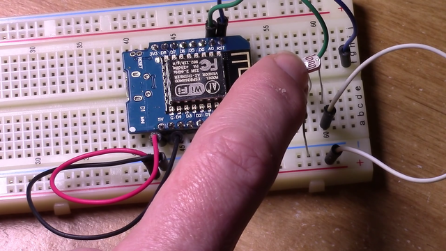
This is the Breadboard.
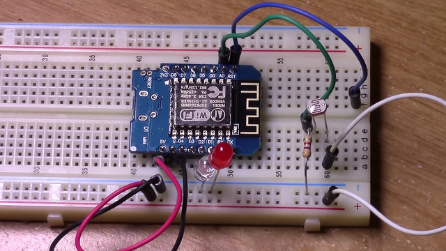
I have set up for the washer or dryer monitor the genetic. We must be on the positive and negative rails are coming off the appreciate places.
I have the Wi-Fi signal LEF on D1
I have the cycle complete notification LED on D1. I have so AO which is the analogue in coming to a light sensor. Which is a 4.7 K resistor going to negative and lights sensor is connected to the positive rail. So what happens when its powered up is that it automatically connect to your Wi-Fi using the information you have provided in the code.
The Wi-Fi LED light will light up notifying you. That does have Wi-Fi connectivity. It does a base flight level check using the light sensor and its records that information.
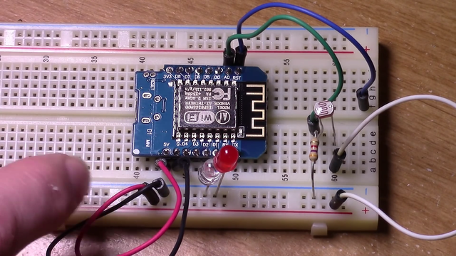
Then it's every 5 second to 30 seconds. Whatever you define the interval eyes. It will sample the light sensor value. Once it senses that the LED on the washer dryer has turned on. Which is set by the threshold value currently at 225 in the base code.
You are welcome to modify that to experiment with it. To see what you need to change for your environment.
It it will set this LED on. Which is a cycle complete LED and then go through the remaining- go through the code to send the pushover notification and it will show up anymore phone or whatever other.
I see you have the Notification set to 3 pushover.
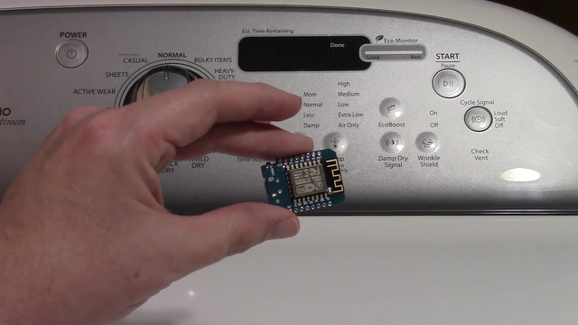
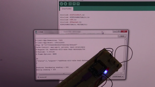
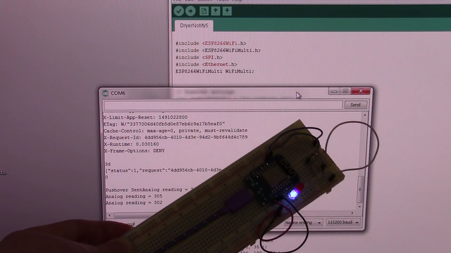
OKay! so the tutorial lights have to be off in order to do this. So what it does not overwhelm the sensor. I am holding this up to the screen. So that you can see the comm monitor as well as the actual device on the breadboard.
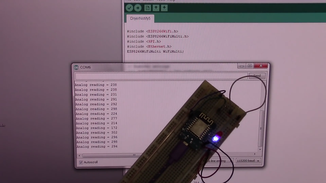
Ok it's initialising…
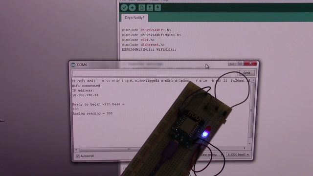
It's connected to Wifi and it's already taken to reading. Because it's a 5 second intervals and analogue reading is 302. Currently out of a 1024 and this is a room with 360 watt LED equivalent bulbs as soon as the cycle is complete.
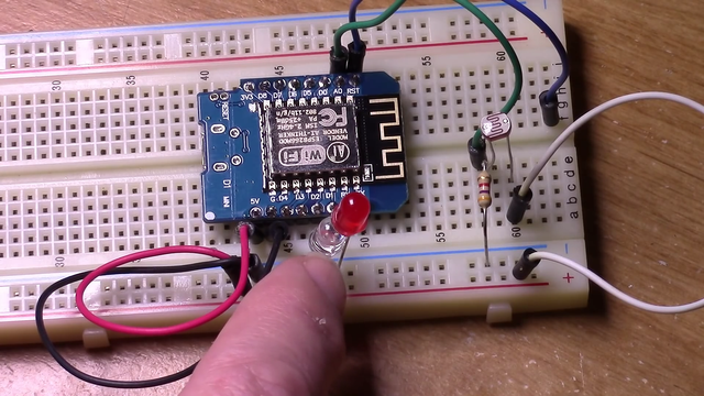
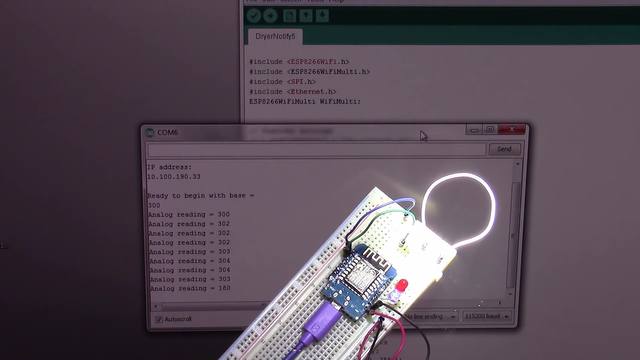
That LED turns on, which I am going to use as a Flashlight the next reading shows the value at a 1020 watt for the red LED shows cycle is complete. And you hear from phone the pushover notification has been sent and you are created to the dryer or washer cycle being completed. Since the light is already off it automatically reset itself running in the cycle competition. LED of and began checking reading again.
After prototyping the components I decided on where a/c DSL that senses the light level as a resistive value a 4.7 K resistor.
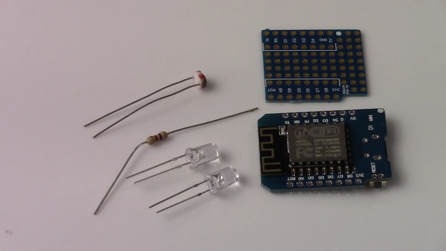
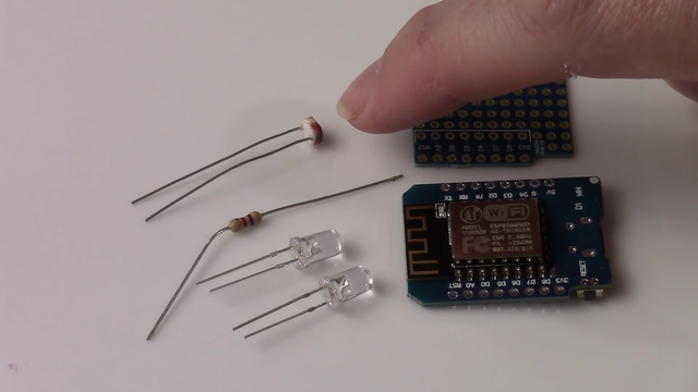
A couple of LED colour is your choice. I went with blue for the Wi-Fi and red for the cycle complete.
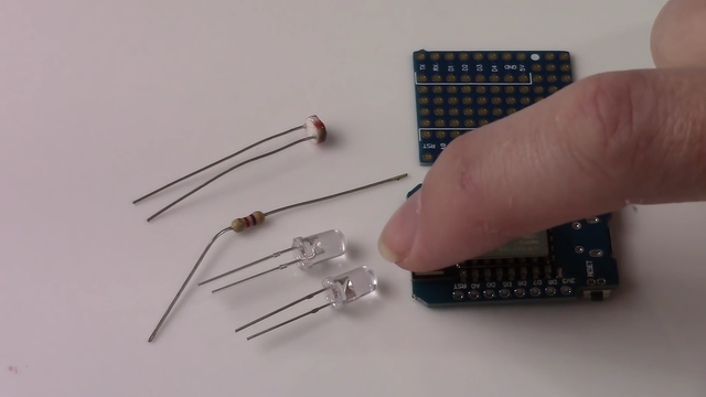
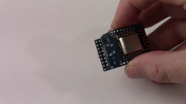
A protoboard that sits with the D1 Mini which is an ESP8266 based Arduino board.
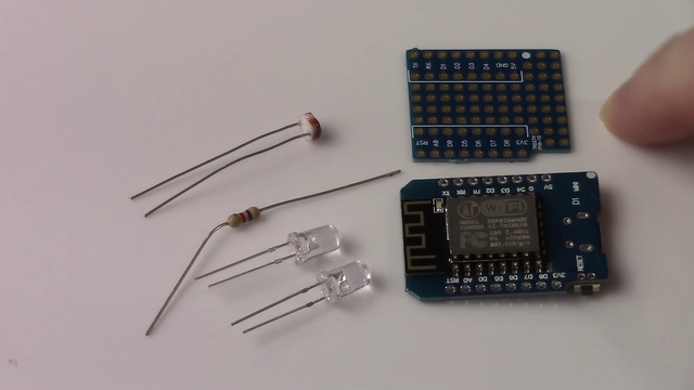
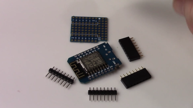
It has onboard Wifi as a standard power connected. this can be had for less than $10 easily anywhere you get them. For protoboard is about $1. Put the D1 Mini board you will need to solder in these headers and then for the proto board or you'll soar in the short socket. After those are soldered in you will have this for the B1 miniboard. Which is what I was using for prototyping on the breadboard and this which is the complete version of the entire circuit on the protoboard, the LEDs, the resistor and the light sensor.
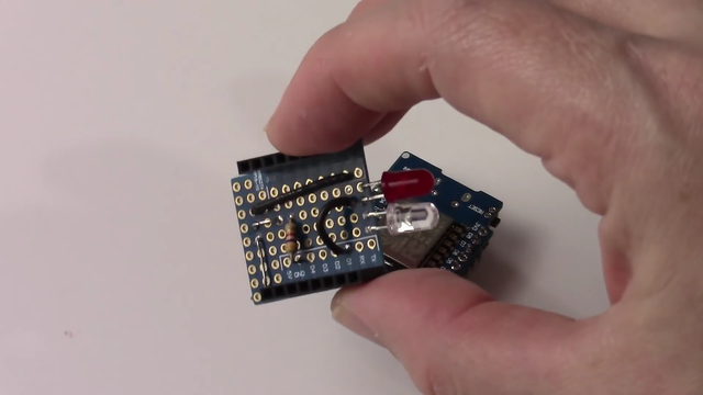
When you are finished soldering the protoboard. You simply plug the ESP8266 into the protoboard and the circuit is complete. You can power it up test it simply by moving.
Having the light sensor down. Moving it into the open light and you will be able to see the entire things function all the changes.
Coding
That you need to make and we are doing on codes should make sense
#include <ESP8266WiFi.h>
#include <ESP8266WiFiMulti.h>
#include <SPI.h>
#include <Ethernet.h>
ESP8266WiFiMulti WiFiMulti;
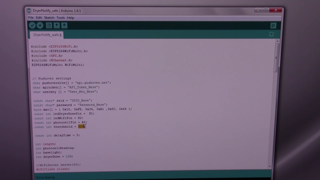
// Pushover settings
char pushoversite[] = "api.pushover.net";
char apitoken[] = "API_Token_Here";
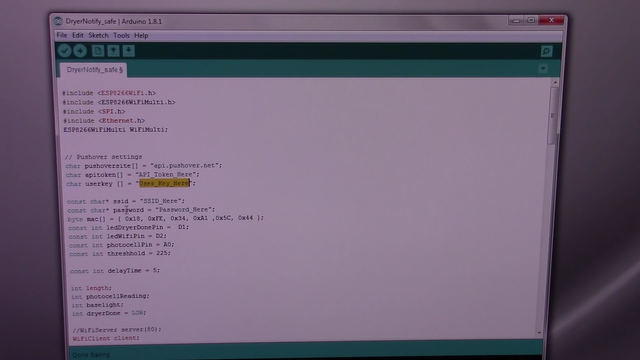
char userkey [] = "User_Key_Here";
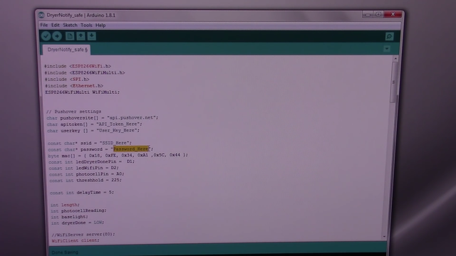
const char* ssid = "SSID_Here";
const char* password = "Password_Here";
byte mac[] = { 0x18, 0xFE, 0x34, 0xA1 ,0x5C, 0x44 };
const int ledDryerDonePin = D1;
const int ledWifiPin = D2;
const int photocellPin = A0;
const int threshhold = 225;
const int delayTime = 5;
int length;
int photocellReading;
int baselight;
int dryerDone = LOW;
//WiFiServer server(80);
WiFiClient client;
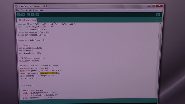
// change network settings to yours
IPAddress ip( 10, 100, 190, 35 );
IPAddress gateway( 10, 100, 190, 254 );
IPAddress subnet( 255, 255, 255, 0 );
char smtpcorp[] = "smtpcorp.com";
int port = 2525;
void setup()
{
Serial.begin(115200);
pinMode(ledDryerDonePin, OUTPUT);
digitalWrite(ledDryerDonePin, LOW);
pinMode(ledWifiPin, OUTPUT);
digitalWrite(ledWifiPin, LOW);
// server.begin();
WiFi.begin(ssid, password);
while (WiFi.status() != WL_CONNECTED) {
delay(500);
Serial.print(".");
}
Serial.println("");
Serial.println("WiFi connected");
Serial.println("IP address: ");
Serial.println(WiFi.localIP());
// delay(5000);
baselight = analogRead(photocellPin);
Serial.println(F("\nReady to begin with base =
"));
Serial.println(baselight);
}
void loop()
{
photocellReading = analogRead(photocellPin);
Serial.print("Analog reading = ");
Serial.println(photocellReading); // the raw
analog reading
if (photocellReading > (baselight + threshhold)) {
if (dryerDone == LOW) {
dryerDone = HIGH;
digitalWrite(ledDryerDonePin, HIGH);
pushover("Dry Cycle Complete");
Serial.print("Pushover Sent");
}
} else {
digitalWrite(ledDryerDonePin, LOW);
dryerDone = LOW;
}
v
if (WiFi.status() == WL_CONNECTED) {
digitalWrite(ledWifiPin, HIGH);
} else {
digitalWrite(ledWifiPin, LOW);
}
delay(1000*delayTime);
}
byte pushover(char *pushovermessage)
{
String message = pushovermessage;
length = 95 + message.length();
if(client.connect(pushoversite,80))
{
client.println("POST /1/messages.json
HTTP/1.1");
client.println("Host: api.pushover.net");
client.println("Connection: close\r\nContent-
Type: application/x-www-form-urlencoded");
client.print("Content-Length: ");
client.print(length);
client.println("\r\n");;
client.print("token=");
client.print(apitoken);
client.print("&user=");
client.print(userkey);
client.print("&sound=falling");
client.print("&message=");
client.print(message);
while(client.connected())
{
while(client.available())
{
char ch = client.read();
Serial.write(ch);
}
}
client.stop();
}
}
But just go over them your pushover settings. You need to change your API token and your user key for your home network. You need to enter SSID here. And the password for that SSID. The threshold is the amount of light change thats need before.
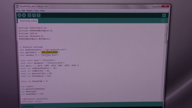

I determine that the cycle is complete and 225 is what. I have been using after some testing and the delay time is how long between checks of the light level.
I would actually go for about 30 seconds.
So that it is not checking continuously it's not really necessary for the washer or dryer. For your own network if you are using a static IP.
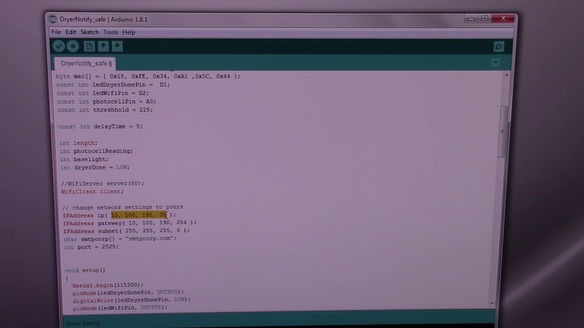
You will need to enter your static IP here your Gateway and subnet. And that should be about if you want to change the notification that is sent to pushover.
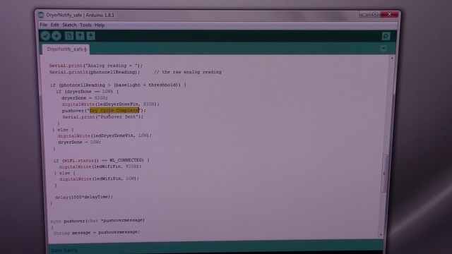
It would be right here you can change dry cycle to wash cycle complete. If you are using this on a washing machine or anything else you would like to say and that's all the changes that needs it.
One more thing if you want to change the sound that push overuse this is the place to make that changed.
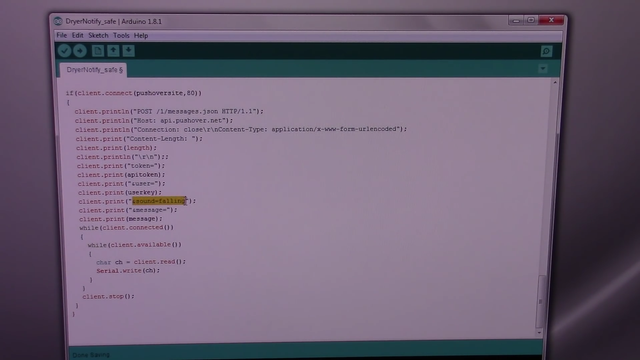
It is in the code you cannot do it on the GUI and they have a list of sounds that you can use. There is a dozen or to pick from and I saw that changes.
We need to make in the arduino codes since the project has been built
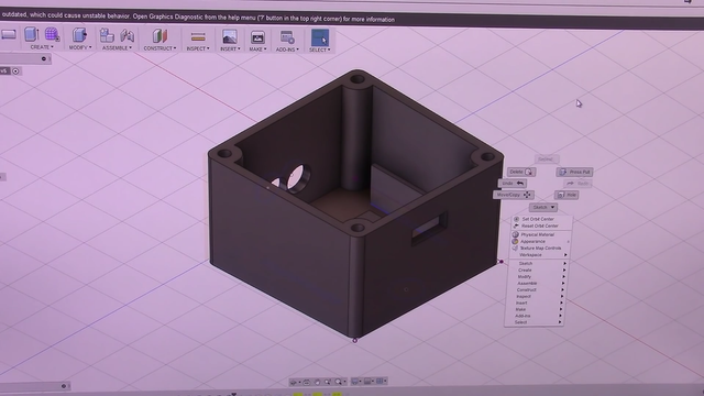
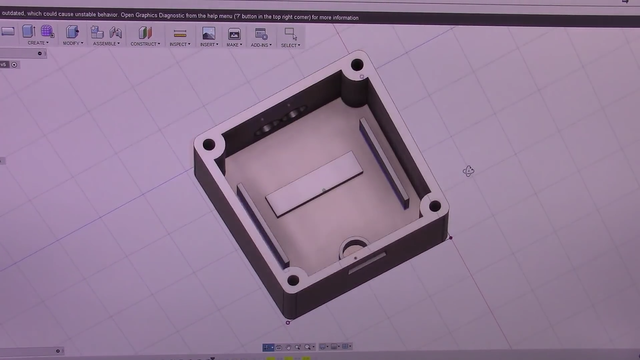
Design
I designed quick box to house the device.
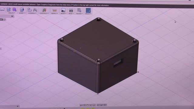
So we have the top layer that Philips around the edge. Make it little nicer and sign these some supports to hold. It in place there is small cylinder that comes up to shield the light sensor. There's the holes for the two LEDs and the hole for the power supply that's coming in and then four screws holes to hold the lid on top. A simple design. It has quite a bit to print through and it look about two and half hours.
So to actually print the complete box.
Actually print the complete box
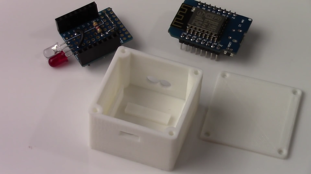
Here's finished box for mountain purpose. since there are no mounting holes for the D1 Mini board or the proto board I am using a small piece of double sided foam tape placed in the bottom on save anything is installed. there should be no result to remove board from the box as you can do all your programming change that need to be made through the micro USB.
So simply slip in protoboard. Making sure the light sensor seats and the hull that position well and enough to fit in a box. Then simply put the mini D1 into the socket and then just screw on the lid.
Unfortunately I don't have any screw the size they are on order. So the rest of this tutorial will be without the screw in place. How do you mount it to the dryer. You could up with just some double sided tape or foam tape onto the face of the dryer.
However that does not remove very well after more than a couple of hours. So what I am often to go with other three empty string they come in different sizes these are the velcros.
They will vellco does and quite a bit of extra high to the base of the box. So what I use grommets. Then I simply glue that with some quick set epoxy on to the face and that gives me the correct height for the when the 3M tape is mounted.
Okay! devices plugged in as you can see it. You need to find where the head LED normally comes on in l. this case it sets a dime and that simply must to be lined up over the top and that's where you will place it.
In any configuration that you desire. I am not interested the Eco monitors so I don't worry about that part.
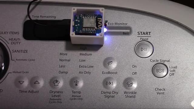
It's ready to go when you start. When the device is initialised is checked the level as long as the LED is off at the time that.
It power up your lesson will be based on the room lighting or slowly black and it does keep some room lighting simply because of the house in whole the dryer cycle is complete sin theta light level change and begins the process of notifying by a pushover through Wi-Fi network that the interprocess when you know that your clothes are done.
Summary
In this tutorial I showed you how to create a push notification device using ESP8226 arduino.
Proof Of Work Done
Curriculum
- My first project about arduino.
Sadly, it was found out that this post is a transcript/copy of an older video on YouTube. Therefore, the Utopian vote will be removed. Utopian is meant only for original and recent work. Any additional submission of content made by someone else or submitting content you made long time ago may lead to no future reviews of your posts.
It has been found that your content is actually plagiarized from existing youtube videos and auto-transcribed into textual format.
Source:
Plagiarism is a serious offense, and accordingly you have been banned from receiving Utopian reviews.
Need help? Write a ticket on https://support.utopian.io/.
Chat with us on Discord.
[utopian-moderator]
You have a minor misspelling in the following sentence:
It should be threshold instead of threshhold.Go here https://steemit.com/@a-a-a to get your post resteemed to over 72,000 followers.
What a technical tutorial but yet basic and simple also
Seems you are just joining steemit, i will advice you to engage more by commenting on other steemians blog and responding to comment on your blog
Nice tutorial again while i await your reply.
Thank you so much @tormiwah for your good advice. I will try...
Congratulations! This post has been upvoted from the communal account, @minnowsupport, by bramvbilsen from the Minnow Support Project. It's a witness project run by aggroed, ausbitbank, teamsteem, theprophet0, someguy123, neoxian, followbtcnews, and netuoso. The goal is to help Steemit grow by supporting Minnows. Please find us at the Peace, Abundance, and Liberty Network (PALnet) Discord Channel. It's a completely public and open space to all members of the Steemit community who voluntarily choose to be there.
If you would like to delegate to the Minnow Support Project you can do so by clicking on the following links: 50SP, 100SP, 250SP, 500SP, 1000SP, 5000SP.
Be sure to leave at least 50SP undelegated on your account.
Join our Discord Channel to connect with us and nominate your own or somebody else's posts in our review channel.
Help us to reward you for making it ! Join our voting trail or delegate steem power to the community account.
Your post is also presented on the community website www.steemmakers.com where you can find other selected content.
If you like our work, please consider upvoting this comment to support the growth of our community. Thank you.
Your support has been removed. Plagiarism of https://www.youtube.com/channel/UChdftwUR90NbYacO-kcvXyg
Thanks for the contribution!
Your contribution has been evaluated according to Utopian policies and guidelines, as well as a predefined set of questions pertaining to the category.
To view those questions and the relevant answers related to your post, click here.
Need help? Write a ticket on https://support.utopian.io/.
Chat with us on Discord.
[utopian-moderator]
Hey @bramvbilsen, your contribution was unvoted because we found out that it did not follow the Utopian rules.
Upvote this comment to help Utopian grow its power and help other Open Source contributions like this one.
Want to chat? Join us on Discord.