Intrusion deterrent system with keypad disarm. (Arduino)
What will I learn
• You will learn function and how to implement a keypad membrane.
• You will learn function and how to use a motion sensor.
• You will learn how these parts fit together and form an anti intrusion system.
• You will get insight to the program code.
Requirement
• Arduino uno
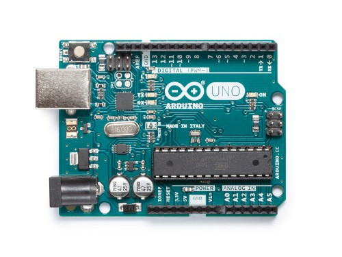
Image source
• 4×3 Keypad membrane
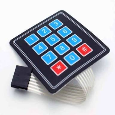
Image source
• PIR motion sensor
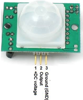
Image source
• LCD 16×02
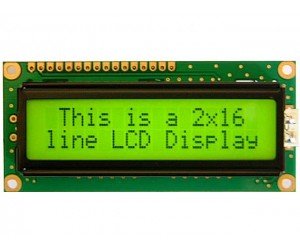
Image source
• Buzzer
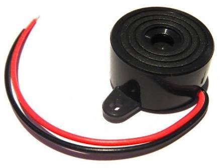
Image source
• Connecting Cables
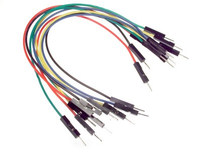
Image source
• USB cable Type A to B
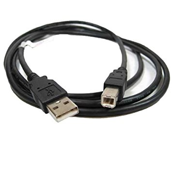
Image source
• Computer

Image source
Software
Arduino software/IDE
Knowledge
• Knowledge of electronic circuit
• Knowledge of programming
Difficulty
Intermediate.
Project description
The project is an embedded system comprising a microcontroller, LCD and motion sensor which can control the action of the buzzer depending on the presence of human detected within 6metres of its range. By using this project we can reduce the human effort in monitoring a valuable item or a keeping a home secured from intrusions.
Components description
• PIR motion sensor: senses/detects human motion within its range approximately within 6metres or 20feet.
• Keypad: allows user to interact with a microcontroller, for inputing of data for locking and unlocking the system
Tutorial content
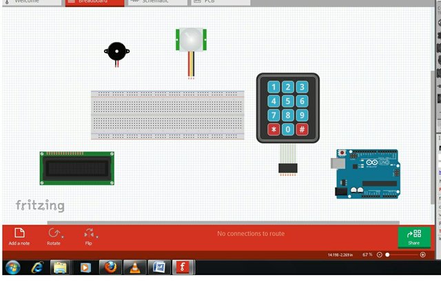
Step 1: Gather all components together
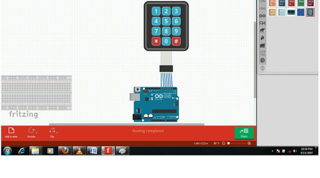
Step 2a: connect keypad to arduino
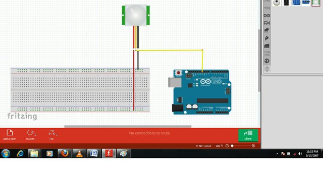
Step 2b: connect pir motion sensor to arduino
Pin 1: 5V VCC. in Red
Pin 2: Output. in yellow
Pin 3: GND. in Black
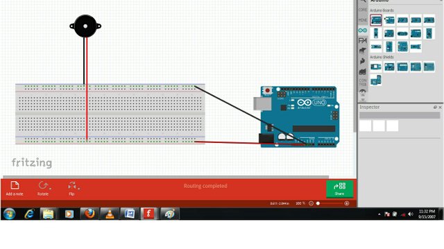
Step 2c: connect buzzer to arduino
Pin 1: 5V VCC. in Red
Pin 2: GND. in black
Step 2d: connect LCD to arduino
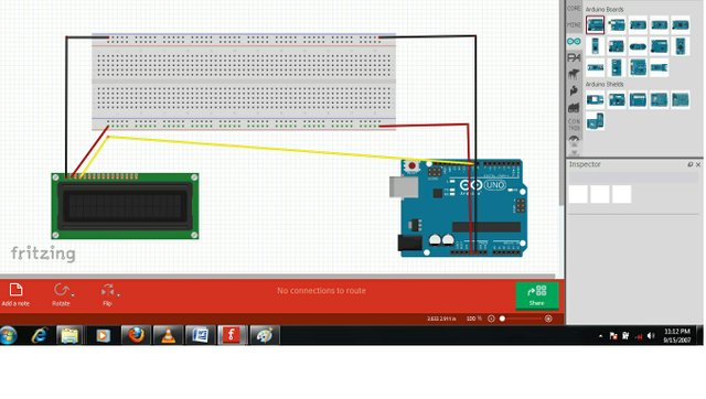
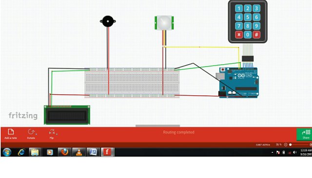
Full setup of connection is as shown below.
Step 3: Programming
• Keypad library setup.
i. Download the keypad library here
ii. Unzip/extract the keypad library
iii. Install the keypad library in your arduino IDE by moving the unzipped folder to: Arduino\Libraries
iv. Restart your arduino IDE
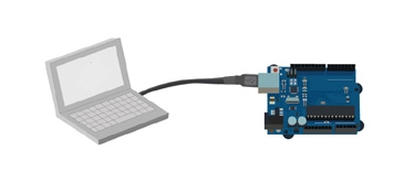
• Connect the set up to the compter
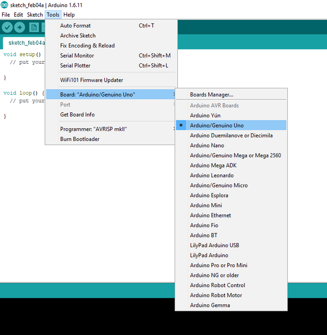
• Once done, open the arduino IDE, go to Tools>Board>then select Arduino/Genuino Uno
• Copy my code below and paste into your IDE.
 *
 * ONCE PIR DETECTES, ITS SOUND AN ALARM
 * ALARM IS DISABLED BY KEYING THE CORRECT PASSCODE.
 */

#include <Keypad.h>
#include <Password.h>
#include<LiquidCrystal.h>
LiquidCrystal lcd(12,11,10,9,8,7); //RS,E,DB4,DB5,DB6,DB7

Password password = Password("1234");
const byte ROWS = 4; //for rows
const byte COLS = 3;  //for columns


//Define the Keymap
char keys[ROWS][COLS] = {
  {'1','2','3'},
  {'4','5','6'},
  {'7','8','9'},
  {'*','0','#'}
};
byte rowPins[ROWS] = {A0,A1,A2,A3}; //connect to the row pinouts of the keypad
byte colPins[COLS] = {A4,A5,2}; //connect to the column pinouts of the keypad
Keypad keypad = Keypad( makeKeymap(keys),rowPins, colPins, ROWS, COLS);

const int BUZZER = 6;
const int PIR = 4;
const int button = 5;
const int LED = 3;
int val = 0;
String code="";

void setup() {
  Serial.begin(9600);
  lcd.begin(16,2);
  lcd.setCursor (2,0);
  lcd.print("ALARM SYSTEM");
  delay(2000);
  lcd.clear();
  pinMode(BUZZER, OUTPUT);
  pinMode(button, INPUT);  //the pin 4 will serve as switch, when it is ON the BURGLAR is ON.....it is connected as an ACTIVE HIGH
  pinMode(LED,OUTPUT);  //this serves as an indicator to show that the ALARM is active to sense motion
  pinMode(PIR, INPUT);
  keypad.addEventListener(keypadEvent); //add an event listener for this keypad
  // put your setup code here, to run once:
  digitalWrite(PIR, LOW);
  digitalWrite(LED,LOW);
  }

void loop() {
  while (digitalRead(button) == LOW){     //the while loop here is set in such a way that the below codes
  lcd.setCursor(1,0);                 //including the if statement depends on pin 4 being ON
  digitalWrite(LED, HIGH);

      val = digitalRead(PIR);
      if (val == HIGH){
         digitalWrite(BUZZER, HIGH);
          lcd.setCursor(0,0);
          lcd.print("  ALARM ON !!!  ");
          lcd.setCursor(0,1);
          lcd.print("PASSCODE:");
          delay(100);
        }

        keypad.getKey();
    }                                  //the while loop covers up to this point
  digitalWrite(LED, LOW);                 //if the digital pin 4 is not HIGH then pin 6
  digitalWrite(BUZZER, LOW);
  lcd.setCursor(0,0);
  lcd.print("ALARM DIS-ARMED ");
  lcd.setCursor(0,1);
  lcd.print("                ");
  delay(200);
  //lcd.setCursor(1,1);
  //lcd.clear();
  if ( digitalRead(button) == LOW){
    lcd.clear();
  }
}

//take care of some special events
void keypadEvent(KeypadEvent eKey){
  switch (keypad.getState()){
    case PRESSED:
  switch (eKey){
    case '#':
    checkPassword();
    break;

    case '*':
    password.reset();
    code ="";
    break;

    default: password.append(eKey);
    code += '*';
    lcd.setCursor(10,1);
    lcd.print(code);

    }
  }
}
void checkPassword(){
  if (password.evaluate()){
    lcd.clear();
    lcd.setCursor(1,0);
    lcd.print("PASSCODE OKAY ");
     digitalWrite(BUZZER, LOW);
     delay(5000);
    password.reset();
    code ="";
    //Add code to run if it works
  }else{
    lcd.clear();
    lcd.setCursor(0,0);
    lcd.print("PASSCODE ERROR ");
     code ="";
    delay(2000);
    lcd.clear();
    password.reset();
    //add code to run if it did not work
  }
}
The program code does the following:
- It initializes the Microcontrollers
- It initializes the Keypad
- It asks you to Input New Password
- It asks you to confirm Password
- It initializes the Sensor PIR
- It initializes the LCD
- It Setups a Continuous loop
- It reads data from Sensor
• Condition 1
-. Is there any Motion?
A. If YES: It initiates a buzzer sound
B. If No: It continues the Loop
• Condition 2
-. Is Correct password inserted?
A. If YES: It deactivates buzzer
B. If No: It continues the Loop
Loop continues to 1.
• Type the code above into the sketch, save and compile the code.
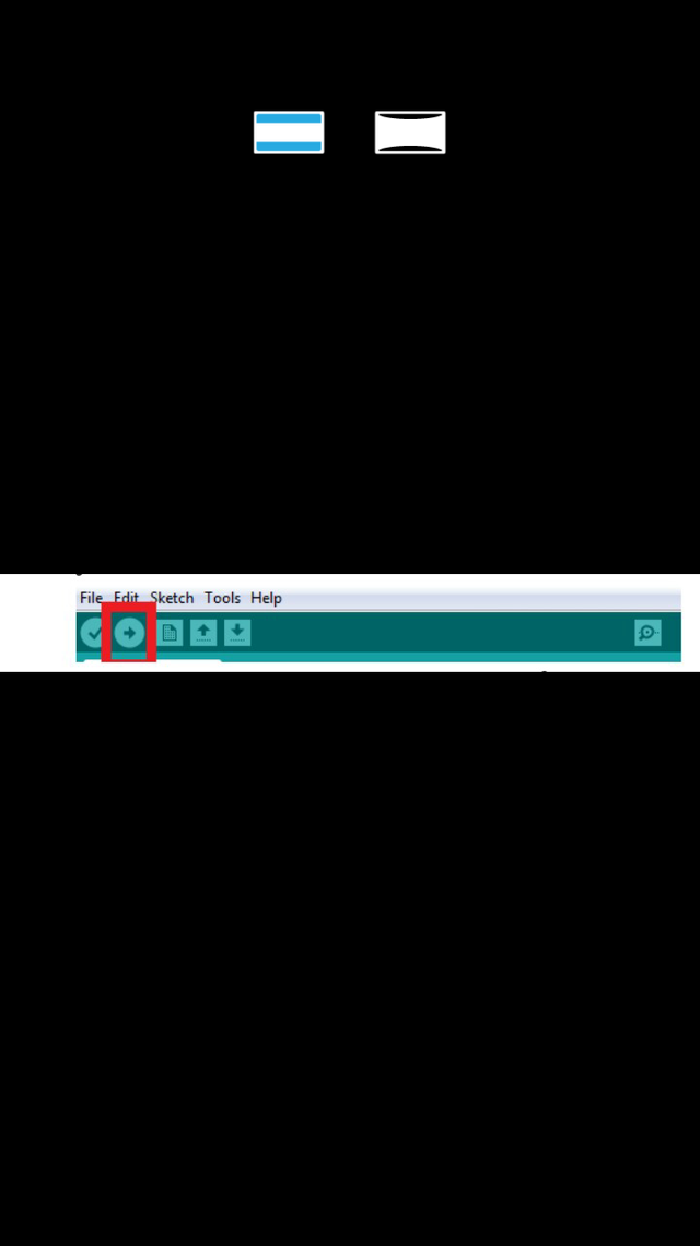
• This will check for errors in the code.
• If there are no errors found, upload the sketch unto the arduino board.
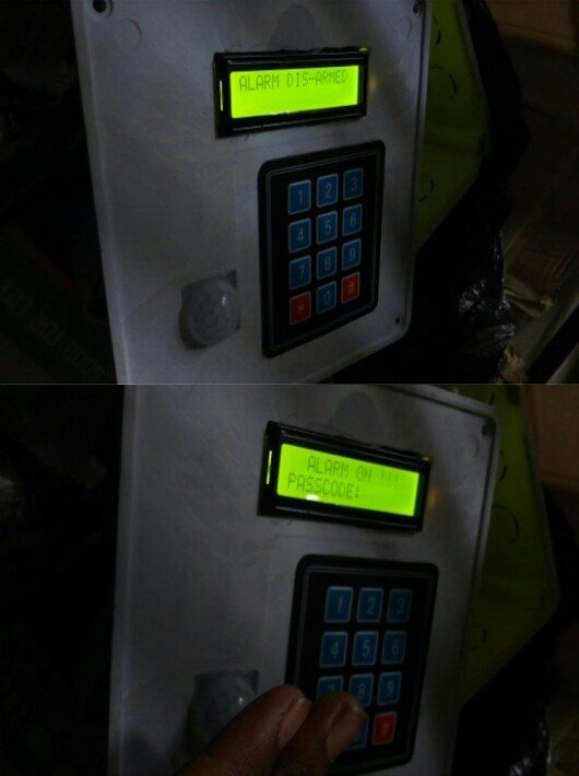
Step 4: Testing
• Having done all the above steps rightly. Power on the project. It will displays as shown below and ask for new user passward input.
Posted on Utopian.io - Rewarding Open Source Contributors
Awesome tutorial
Thanks. Glad you enjoyed it.
Congratulations! This post has been upvoted by SteemMakers. We are a community based project that aims to support makers and DIYers on the blockchain in every way possible. Find out more about us on our website: www.steemmakers.com.
If you like our work, please consider upvoting this comment to support the growth of our community. Thank you.
Thank you for the contribution. It has been approved.
You can contact us on Discord.
[utopian-moderator]
Thank you.
Hey @daniel-itunu I am @utopian-io. I have just upvoted you!
Achievements
Community-Driven Witness!
I am the first and only Steem Community-Driven Witness. Participate on Discord. Lets GROW TOGETHER!
Up-vote this comment to grow my power and help Open Source contributions like this one. Want to chat? Join me on Discord https://discord.gg/Pc8HG9x
Good post!
I use arduino for my projects too, but community on steem dont worry about it.
Great.
Good to connect with you.
Resteemed by @resteembot! Good Luck!
Curious? Read @resteembot's introduction post
Check out the great posts I already resteemed.
ResteemBot's Maker is Looking for Work
Wow, this is lovely. I learnt a lot here. Basically, my colleagues in the Electrical Electronics department used the arduino software sometimes ago for a control system. I'm just knowing in depth what is really entails and I'm very impressed with the way you presented it.
Keep steeming!
Woops, i didn't know it was you. I was referring to you guys earlier up there (ELE guys). Well-done bro
Thanks bro!!
Your Post Has Been Featured on @Resteemable!
Feature any Steemit post using resteemit.com!
How It Works:
1. Take Any Steemit URL
2. Erase
https://3. Type
reGet Featured Instantly & Featured Posts are voted every 2.4hrs
Join the Curation Team Here | Vote Resteemable for Witness