Remote decoding for control operations of projects (ON/OFF LED action as a case example) [Arduino]
What will I learn
• You will learn how to decode a remote controller to obtain hexadecimal values behind every button.
• You will learn the function of “TSOP382” Infrared Red receiver and why its a better product.
• You will learn how these parts fit together .
• You will learn how these decoded hexadecimal values
can be used to set buttons to perform a simple ON LED action.
• You will get insight to the program code.
Requirement
• Arduino uno
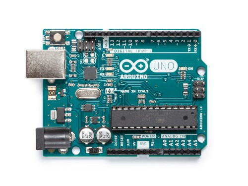
Image source
• TSOP382 IR receiver sensor (38KHz)
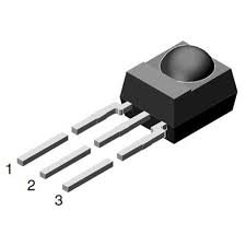
Image source
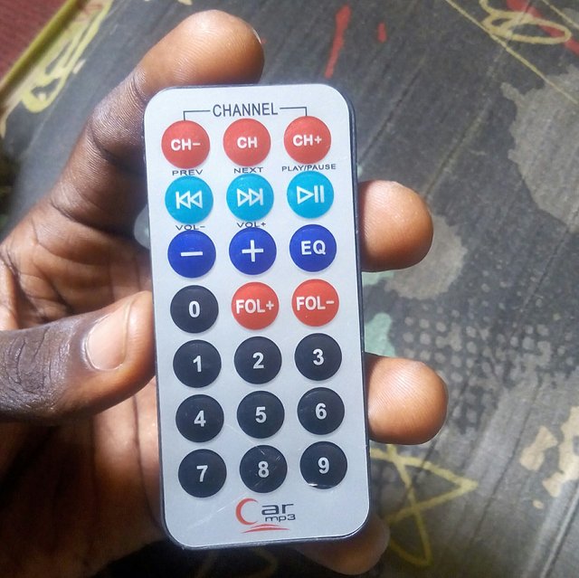
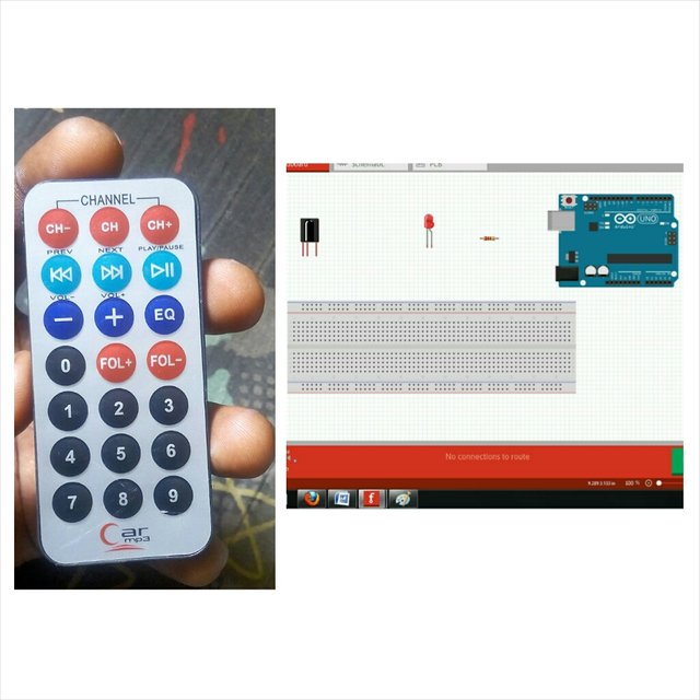
• Remote controller (preferrably NEC or Sony)[I will be using a NEC coded mp3 controller]
• LED
Image source
• Resistor 330ohms
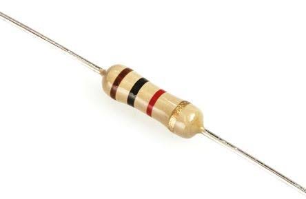
Image source
• Connecting Cables
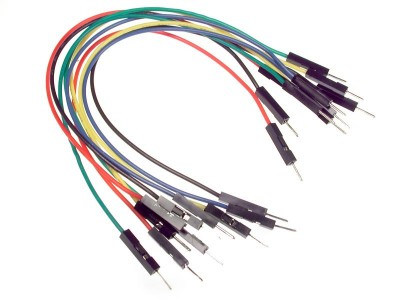
Image source
• USB cable Type A to B
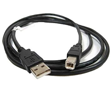
Image source
• Computer

Image source
Software
• Arduino software/IDE
• Arduino IR library
Knowledge
• Knowledge of electronic circuit
• Knowledge of programming
Difficulty
Intermediate.
Project description
The project provides basic step tutorials on how to decode a remote controller to obtain the hexadecimal values behind every button. These hexadecimal values are used in the program code to perform any remote operation such as switching ON/OFF a LED as illustrated in this project tutorial or other numerous operations of control.
Components description
• TSOP382 IR receiver sensor: it receives a 38KHz frequency signal. Many IR receivers give false detection when used in sunlight or regions of light rays. TSOP382 is a complex and sophisticated sensor that can differentiate between actual signal sent from IR remote and that from sunlight or light rays. It operates at 38KHz, receives the signal, filter the noise and extract the original signal
• IR remote: this sends out pulses of infrared light that represent specific binary codes. These codes are received by the IR receiver sensor(TSOP382 in this case).
Tutorial content
Step 1: Gather all components together
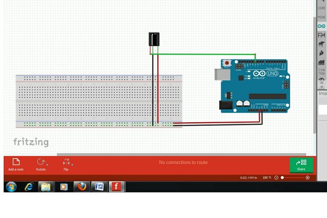
Step 2a: connect TSOP382 IR receiver to arduino
Pin 1: Ouput. in Green
Pin 2: GND. in Black
Pin 3: 5V Vcc. in Red
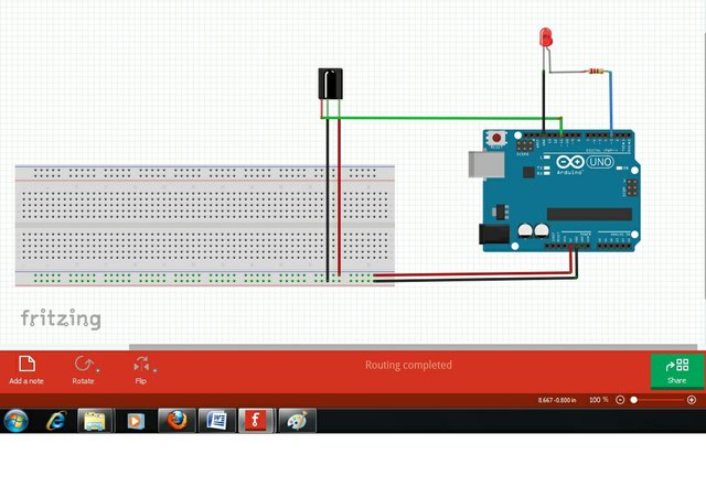
Step 2b: full setup (resistor value is 330ohms)
Step 3: Programming
• IR library setup.
i. Download the IR library here
ii. Unzip/extract the IR library
iii. Install the IR library in your arduino IDE by moving the unzipped folder to: Arduino\Libraries
iv. Restart your arduino IDE
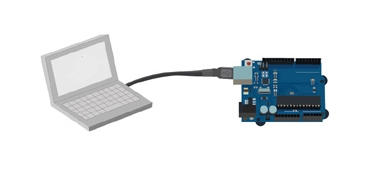
• Connect the set up to the compter
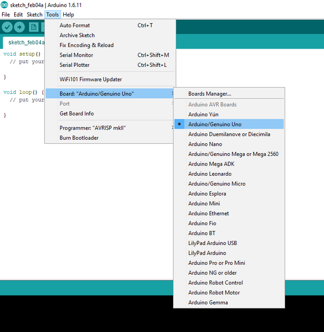
• Once done, open the arduino IDE, go to Tools>Board>then select Arduino/Genuino Uno
• Copy and upload this sketch below into arduino.
#include <IRremote.h>   // use the library

int tsopreceiver = 11; // pin 1 of IR receiver to Arduino digital pin 11

IRrecv irrecv(tsopreceiver); // create instance of 'irrecv'

decode_results results;

void setup()

{

Serial.begin(9600); // for serial monitor output

irrecv.enableIRIn(); // Start the receiver

}

void loop()

{

 if (irrecv.decode(&results)) // have we received an IR signal?

{

Serial.println(results.value, HEX); // display it on serial monitor in hexadecimal

irrecv.resume(); // receive the next value

}  // Your loop can do other things while waiting for an IR command
}
We need to decode that is know what values are sent to the TSOP382 receiver when any of the remote button is pressed. This code enables us to know the values of the remote buttons whenever any button is pressed.
IR receiver output pin is at 11 since thats the connection port used in the circuit.
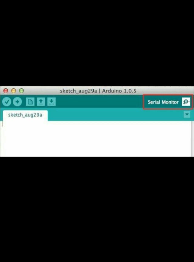
• Open the serial terminal at 9600 Baud rate to see what values are sent to the receiver in Hexadecimal values. To open click on serial monitor located on the far right top corner on the arduino screen.
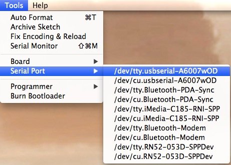
• Go to Tools>Serial port and select the right port of your connection.
• Press any key on the remote while pointing it towards the IR receiver.
• You will see some Hexadecimal values when pressing the button as shown here.
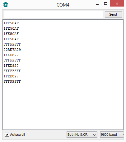
• Make sure to note these values or write them down.
• Repeat a number of times and make sure you are getting the same Hexadecimal value for a single button. If you aren’t getting same value for a single button, this is due to incompatible remote. So make sure to use NEC or Sony remote as recommended.
• Here are few of my decoded values from my above snapped remote.
0xFF30CF for button 1
0xFF18E7 for button 2
0xFF7A85 for button 3
0xFF10EF for button 4
0xFF38C7 for button 5
0xFFA25D for button CH-
0xFF629D for button CH
0xFFE21D for button CH+
0xFF22DD for button PREV
0xFFE01F for button VOL-
0xFFA857 for button VOL+
• Now you can use any of the decoded values to perform any action in your program code such as switching ON a LED or other control activities.
• Lets go ahead and use one of our decoded values to ON a LED using my button 1 on the remote as ON button.
• My button 1 on the remote has a Hexadecimal code of
0xFF30CF. I will use this code in my the program code to set the buttion as the ON switch button for the LED.
• Type or copy and paste the code below to your IDE.
    #include <IRremote.h>

    int tsopreceiver = 11; // the pin where you connect the output pin of TSOP382
    int led1 = 3;
    int itsONled = 0;
    /* the initial state of LED is OFF (zero)
    you can change the zero to 1 if you want the
    led to light when the board is powered */
    #define code1  0xFF30CF// code received from button 1

    IRrecv irrecv(tsopreceiver);

    decode_results results;

    void setup()
    {
      Serial.begin(9600);   // you can comment this line
      irrecv.enableIRIn();  // Start the receiver
      pinMode(led1, OUTPUT);
    }

    void loop() {
      if (irrecv.decode(&results)) {
        unsigned int value = results.value;

            if(itsONled == 1) {        // if led is on then
                digitalWrite(led1, LOW);   // turn it off when button is pressed
                itsONled= 0;           // and set its state as off
             } else {                      // else if first led is off
                 digitalWrite(led1, HIGH); // turn it on when the button is pressed
                 itsONled= 1;          // and set its state as on
             }

        }
        Serial.println(value); // you can comment this line
      }
Code break down.
First, we added the library for the IR receiver and remote. Then defined the key for the button to be used in the program which is;
"#define code1 0xFF30CF// code received from button 1"
you can use your own Hexadecimal value as this will be shown on your serial monitor as explained.
Next we defined the pin where we connected the LED. Which is; "int led1 = 3;"
In the setup function, we defined the LED pin as the output pin, because we are giving the output to the LED through those pin. Which is; " pinMode(led1, OUTPUT)"
In the loop function, first, we check if any key has been pressed. If any key has been pressed, then it compares that key with the key that we have defined in our code which is 0xFF30CF for my remote type. If the key matches, then the LED connected turns up. If the LED connected is already lit up, then it goes off.
if (irrecv.decode(&results)) {
        unsigned int value = results.value;

            if(itsONled == 1) {        // if led is on then
                digitalWrite(led1, LOW);   // turn it off when button is pressed
                itsONled= 0;           // and set its state as off
             } else {                      // else if first led is off
                 digitalWrite(led1, HIGH); // turn it on when the button is pressed
                 itsONled= 1;          // and set its state as on
             }

        }
        Serial.println(value); // you can comment this line
        irrecv.resume(); // Receive the next value
      }
• Save, compile and Upload the sketch below to your arduino.
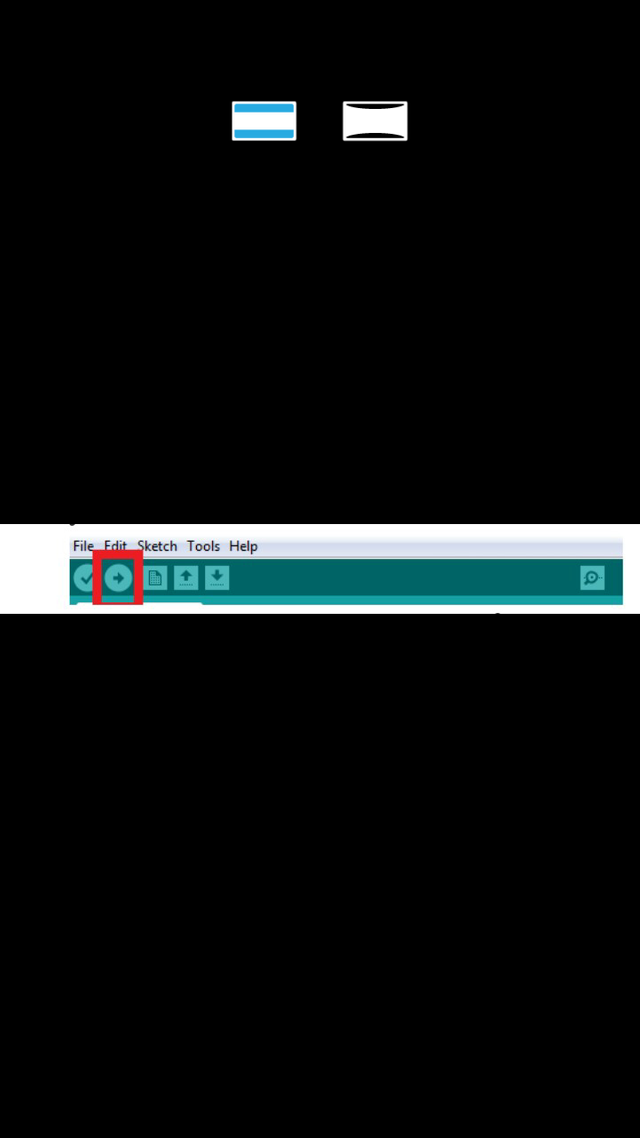
• This will check for errors in the code.
• If there are no errors found, upload the sketch unto the arduino board.
Step 4: Testing
• Having done all the above steps rightly, we have decoded our remote and set desired value into the program code to ON a LED.
• Power on the project, the initial state of the LED is off. Press the button 1 and the LED comes on.
Curriculum
Posted on Utopian.io - Rewarding Open Source Contributors
Great post and I Like your post.
Thanks.
Glad you did!
Congratulations! This post has been upvoted by SteemMakers. We are a community based project that aims to support makers and DIYers on the blockchain in every way possible. Find out more about us on our website: www.steemmakers.com.
If you like our work, please consider upvoting this comment to support the growth of our community. Thank you.
Resteemed your article. This article was resteemed because you are part of the New Steemians project. You can learn more about it here: https://steemit.com/introduceyourself/@gaman/new-steemians-project-launch . If your post has more upvotes, your post will appear in the trending page. To get more upvotes, you can bid for @steembidbot vote. please check it out here: https://steembottracker.com/
Your contribution cannot be approved because it does not follow the Utopian Rules.
Violated Rule(s):
My Opinion(s):
You can contact us on Discord.
[utopian-moderator]