Microcontroller Programming using MikroC & Fritzing for circuit design: A step by step process in PIC programming of the basic 7-segment display common cathode
Hello everyone!
This is my 4th contribution , though my 3rd contribution was not approved. I hope you already read my first & second contribution. In this contribution, it’s quite different from the previous one because I will show you how to program the basic 7 segment display for a common cathode.
Let’s start with the materials and software that we will be using in this topic
Materials
♦ Push button
♦ Capacitor
♦ Crystal oscillator
♦ Seven segment
♦ PIC16F84A
♦ Resistor
#Software
◘ Fritzing
◘ MikroC compiler for PIC
Desired Output Display
Our desired output is to show the 7-segment display (common cathode) from 0-9.
But for the sake of originality, I will include “RFECE143” as an output.
Part 1: MikroC compiler for PIC
Step 1. Open mikroC
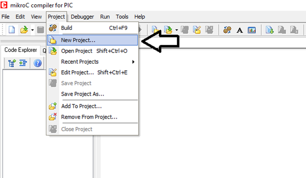
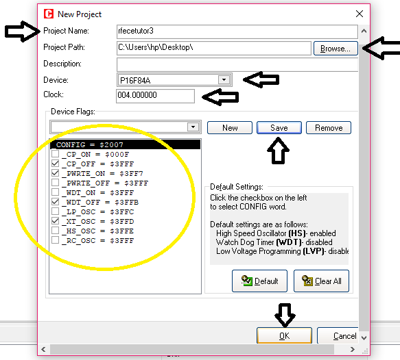
Step 2. Click the “New Project” for us to create our third tutorial. Input our project name , example “rfecetutor3”, project path is the folder path we like to save our project. The device we will use, the PIC16F84A. Check the necessary configuration as you can see in the picture below. Click “save” then click “ok”.
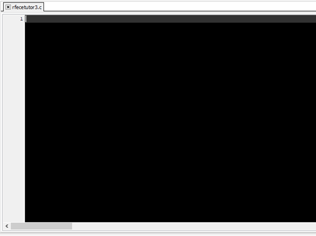
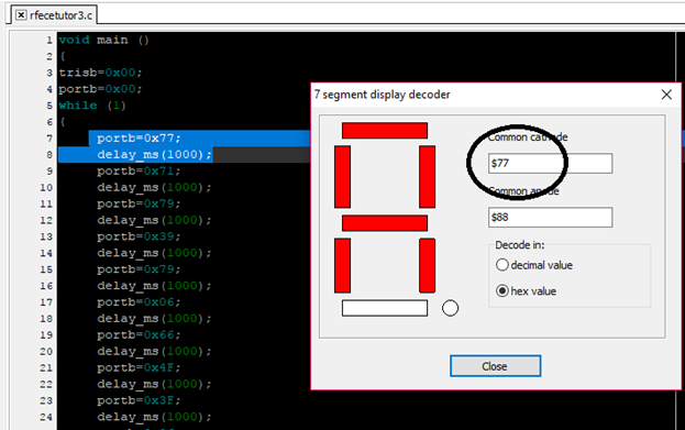
Step 3. New window will pop up. With the project name “rfecetutor3”. In this window, we will program our codes. So here, I have created my own program. Programming is an art, so you can create or program with your own strategy. The shorter the codes the better, because it can only consume small memory size.
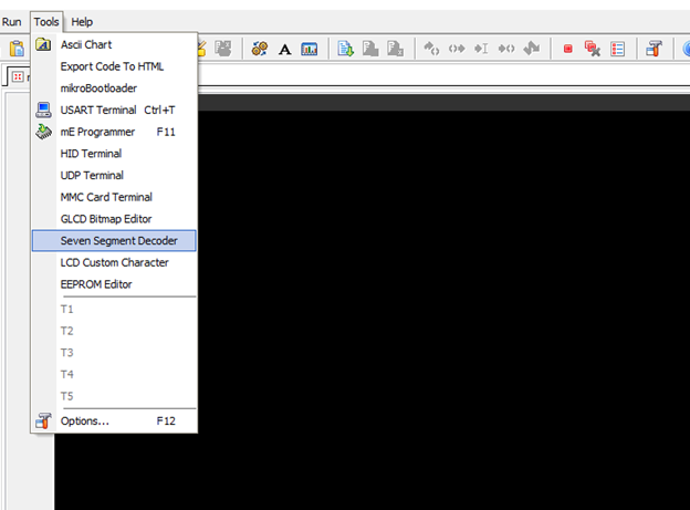
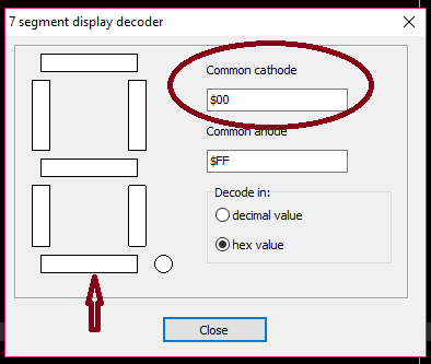
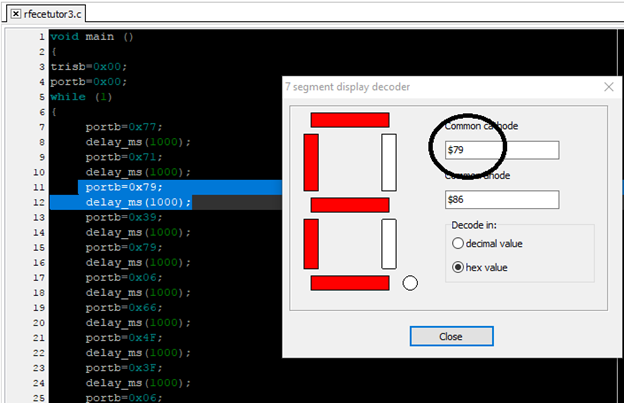
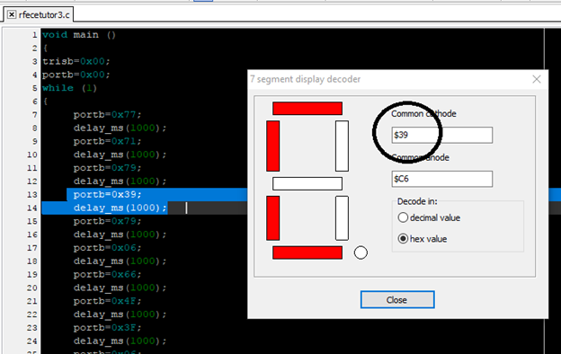
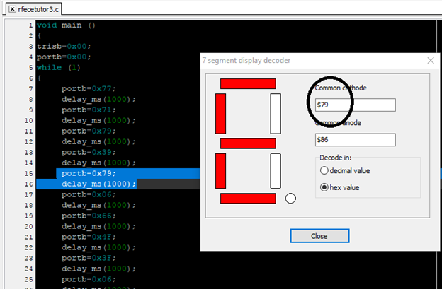
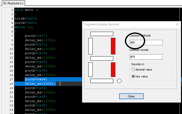
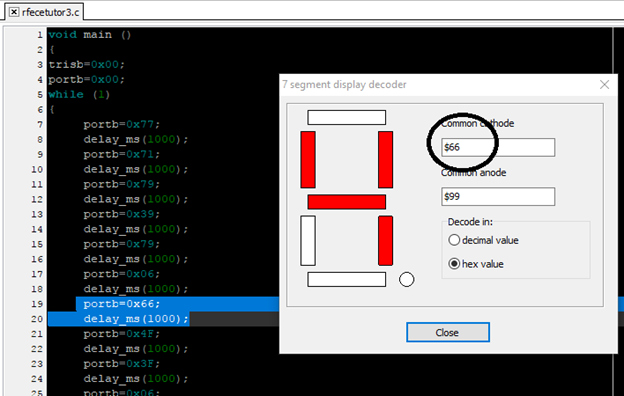
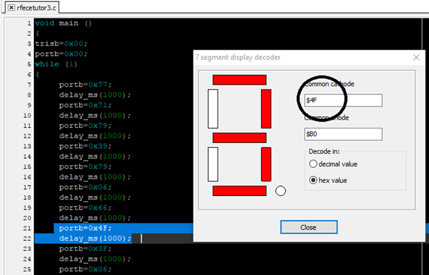
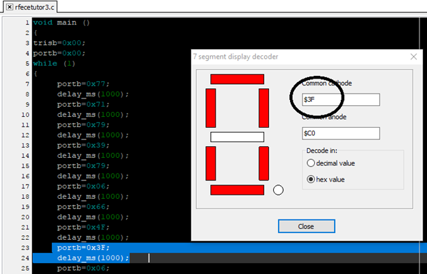
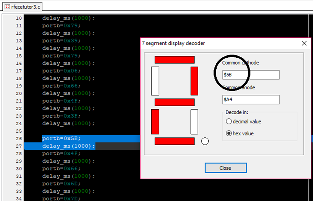
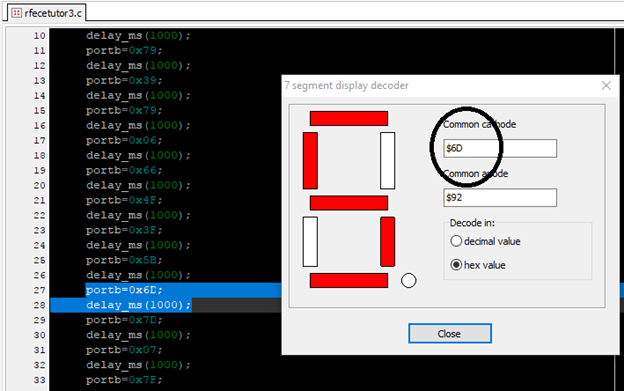
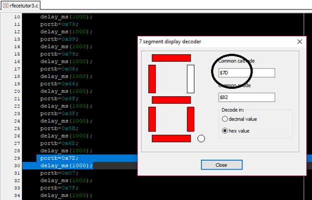
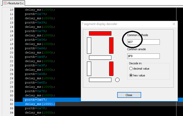
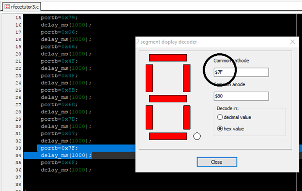
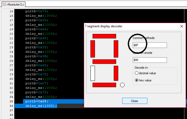
Step 4. For this topic, we will focus on the output of the seven segment display. So we need to decode the hex value of each display we want to see. Because we need to know each hex value for our program codes. Click on “Tools” then click on “seven segment decoder”.
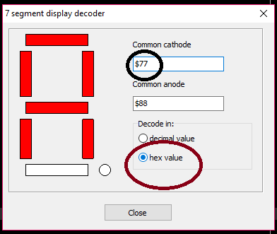
Step 5. New window will appear , the 7 segment display decoder. Click on each rectangle to form the display you want to see. Choose hex value for the decode in.
For example, the letter “R”. The hex value is 77.
Step 6. We will start our program codes.
Step 7. Click build project to see if we have errors. In this activity, it’s a success. So it means, our codes were correct.
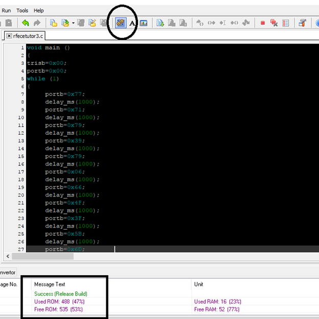
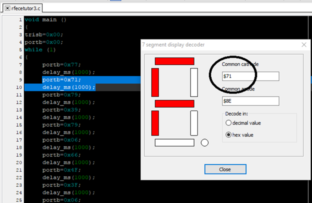
These are codes that I had program for this tutorial
void main ()
{
trisb=0x00;
portb=0x00;
while (1)
{
     portb=0x77;
     delay_ms(1000);
     portb=0x71;
     delay_ms(1000);
     portb=0x79;
     delay_ms(1000);
     portb=0x39;
     delay_ms(1000);
     portb=0x79;
     delay_ms(1000);
     portb=0x06;
     delay_ms(1000);
     portb=0x66;
     delay_ms(1000);
     portb=0x4F;
     delay_ms(1000);
     portb=0x3F;
     delay_ms(1000);
     portb=0x5B;
     delay_ms(1000);
     portb=0x6D;
     delay_ms(1000);
     portb=0x7D;
     delay_ms(1000);
     portb=0x07;
     delay_ms(1000);
     portb=0x7F;
     delay_ms(1000);
     portb=0x6F;
     delay_ms(1000);
}
}
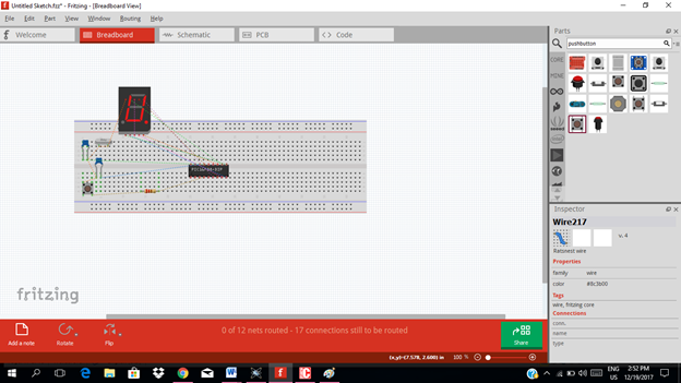
Part II. Circuit design using Fritzing PCB layout
1. Schematic diagram of our activity
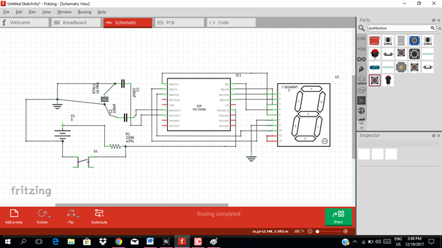
In pcb layouting, you can design your own style. Or you can use the breadboard in designing.
Application of this activity
In our daily life, we already experience using this 7 segment display, like when we use alarm clock, when we go shopping at the counter area or even when we process documents we have to see priority number display.
In most digital systems, we need to display the output of our chip for example clock & calculation results on an external hardware. One conventional method of doing this is using an array of 7-segment displays.
The capacity to learn is a gift; the ability to learn is a skill; the willingness to learn is a choice.
Brian Herbert
Thanks for dropping by everyone! :-) :-) :-)
Yours truly
RFECE143
Posted on Utopian.io - Rewarding Open Source Contributors
Nice post, beautifully presented and explained. Detail oriented with nice pics. Thank you for sharing this with us, Upvoted ...
Thank you so much @kingjan ..:-) I'm glad that you like it..:-)
Thank you for the contribution. It has been approved.
You can contact us on Discord.
[utopian-moderator]
Thank you @shreyasgune ..:-)
Good post, like the previous ones.
At university I learned just how to program Atmel microcontrollers and now I see that the programming of PICs is similar.
Thanks @rpsreal ..yeah they have similarities at all.
Ayrıntılı bilgi için teşekkür ederim
rica ederim @thegossip
Hey @rfece143 I am @utopian-io. I have just upvoted you!
Achievements
Suggestions
Get Noticed!
Community-Driven Witness!
I am the first and only Steem Community-Driven Witness. Participate on Discord. Lets GROW TOGETHER!
Up-vote this comment to grow my power and help Open Source contributions like this one. Want to chat? Join me on Discord https://discord.gg/Pc8HG9x
informative and a great help. nice post @rfece143, keep it up!